magnumP5's RX-7 Build Thread

This makes me glad i didnt build my own harness...

I love the alternator relocation. Still wanna know if i could do it...
 
Loving the progress, Jon. While I'm doing my wiring I just ask myself WWJD (Jon), since Jesus doesn't know wiring. And that radiator is huge! Looking good. :)
LOL as long as it has nothing to do with the loom I'll take that as a compliment!

This makes me glad i didnt build my own harness...

I love the alternator relocation. Still wanna know if i could do it...
It's that bad huh? It would've been a lot easier had I decided to remove the master cylinders and brake booster but I really didn't want to do that. When this car does inevitably become "racecar" I'll probably go back and redo everything; like rewire the entire "car everything."

The alternator relocation bracket is pretty simple. I probably could've made my own but it wouldn't look as nice. When I tear down the engine I could try to pick off some dimensions if your interested. I can't recall if you're going to have A/C or P/S but my relocation bracket doesn't work with either.

I didn't get anything done last night - yardwork needed doing. I plan to resume car work tonight and plan on knocking out the alternator wires. One thing that's gotten me concerned are all the power wires in the engine bay that have the contact points "exposed" at the circuit breaker. I'm not really sure how to go about covering these or if it even poses a problem.

Good news! Mazdatrix got my parts and everything arrived undamaged. Those guys are pretty serious about balancing - they called and asked specifically what kind of apex seals I'll be using (steel, carbon, ceramic, 1-piece, 2-piece, 3-piece, 2 mm, or 3 mm). Can't wait to get everything back!
 
I didnt mean it in a bad way...

But if i did my own i wouldve done it with milspec connectors and such.

My harness will also be tucked. But i didnt mean to come off negative towards your harness and wiring job.

Just meant i hate wiring and that looks like a lot if work...
 
I didnt mean it in a bad way...

But if i did my own i wouldve done it with milspec connectors and such.

My harness will also be tucked. But i didnt mean to come off negative towards your harness and wiring job.

Just meant i hate wiring and that looks like a lot if work...
Gotcha. If it ever becomes "racecar" I want to seal every hole in the firewall except that for the steering column and use bulkhead connectors. Most of the harness on the driver's side wasn't engine-related so I removed very little from stock so it seemd best to leave it there and add to it rather than redo everything. I never saw the purpose of using Mil-spec connectors in cars; it just doesn't seem worth the cost and it's really only for the "look" in most cases. I'm guilty of using Mil-spec wire but that's because I was looking for multi-colored wire and a Mil-spec source was the only place where I could get small quantities. The smaller overall diameter is nice, plus it's lighter! I didn't tuck the harness because if something went haywire on track I want to be able to quickly assess without having to remove fenders and such.

Made (slow) progress last night. The alternator is fully wired now:

20120912_201802.jpg


They sit higher than I had originally thought, which means the plug wires will be closer; hopefully that doesn't cause a problem. It's starting to look more like a complete engine bay though. All that's left is the starter power wire, plug wires and trimming the transmission harness. Still need to figure out the radiator ducting and I really want to TII hood to play with.
 
Took measurements for plug wires and got the starter cable completed yesterday. Here's the end result:

20120913_201909.jpg


The starter wire snakes along the frame rail next to the main harness and passes under the steering column to the starter:

20120913_201954.jpg


I'm really not happy with how I have three wires attached to one post on the circuit breaker. I really don't like how the starter wire loops around like it does but I haven't come up with another solution to that with the current setup. The more I think about it I want to move the circuit breaker further back by the strut tower and then run a shorter lead to a bus bar where the breaker currently is and have the main fuse box, fan, and starter power wires connect from there. Currently looking at something like this: https://www.vtewarehouse.com/content/electromech/busbar/html/large4point/l4point.php because of the available cover to protect against shorts.
 
Thank you for that link, Jon. So, sorry for the newb question, but you would run your main positive battery cable to that, then from the block to your starter and fuse box?
 
Thank you for that link, Jon. So, sorry for the newb question, but you would run your main positive battery cable to that, then from the block to your starter and fuse box?
My plan was:

main power -> circuit breaker -> bus bar -> engine fuse box, starter, fan relay

However, your question has me thinking if I really need that circuit breaker at all. I already have one breaker <12" from the battery in the car. The main power wire runs into the engine bay to the second circuit breaker. From there power goes to the starter directly, to the electric via via an inline 20A fuse and a relay, and the engine fuse box, which is connected to the alternator via a 100A fuse. Is the second circuit breaker really needed if the fan relay and alternator are already fused? The only thing that wouldn't be fused is the starter. If I can ditch that second circuit breaker my life becomes much easier.
 
Umm, yeah... that's what I was thinking too... ;)

30d43_funny-dog-pictures-i-have-no-idea-what-im-doing.jpg

LOL, awesome picture. I'm sure this is how I look when I'm in the garage staring at the car scratching my head. From the little research I've been able to find specific to the RX-7 (mostly FD's) it really doesn't seem like the second breaker in the engine bay is needed. The battery is protected by the first breaker and the alternator should be protected by the 100A fuse in the fuse box. Since the starter will only be receiving power from the battery or the alternator (barely any) the breaker and 100A fuse would trip if excess current is drawn. That being said I'm going to go about replacing the breaker in the engine bay with that four post bus bar I linked earlier. Unfortunately I now have to wait for more parts and probably make a couple new wires...

Oh yeah, I forgot to mentioned that when I got everything wired last night I plugged the battery back in to check the system. Recall I had changed my primary ground from the chassis to the engine a while back but I had never checked the system. Turns out everything still works! I even cranked the starter a few times to check my wiring and it happily spun away. I'm definitely going to have to keep this battery on a trickly charger though...
 
The extra breaker is a bit overkill. You'd be fine without it.
 
The extra breaker is a bit overkill. You'd be fine without it.

I ordered some parts and I'm going to try out a couple different things and go with what's cleanest. I fear the bus bar is going to be too big so I'm going to try a single post solution as well.
 
How big of a bus bar are we talking?

The one in the link above is about 6.5" long, 1.5" wide, and like 2" tall and has four 5/16" terminals. I'm not sure why it's so big for only four terminals but that seems par for the course with bus bars. I don't know why it's so hard to find a simple 4 terminal power distribution block that can handle 150A. I've been looking at bus bars because all the distribution blocks I see are the screw type primarily used in audio applications.
 
Ordered the plug wires Friday on the way home from work. Yeah, it was that easy. I'll highly recommend Magnecor to anyone. Just make sure you know what you want upfront (familiarize yourself with their catalog). The conversation literally went like this:

Me: Hi I'd like to order some custom spark plug wires.
Magnecor Rep: What kind of car is this for?
Me: '89 Mazda RX-7 with the 1.3L rotary, but I've moved the ignition components all around and I have aftermarket coils.
Magnecor Rep: Okay, so what were you looking at?
Me: Your KV85 wires in the "C" configuration, 30 inches long.
Magnecor Rep: So that's the 8.5 mm race wire with 90 deg HEI-type ignitor terminals and straight spark plug terminals?
Me: Yep, that sounds right. I'd also like to pick up two sets of your wire organizers.
Magnecor Rep: No problem. Anything else?
Me: Just a quick question. Since I estimated the wire lengths and erred on the long side, if they're too long could I send the wires back to be shortened?
Magnecor Rep: No that won't be a problem.

All that and I was told they should ship today. Total cost was $110 including shipping. That's hard to beat considering the cost of decent wires, terminals, and the proper crimping tool.

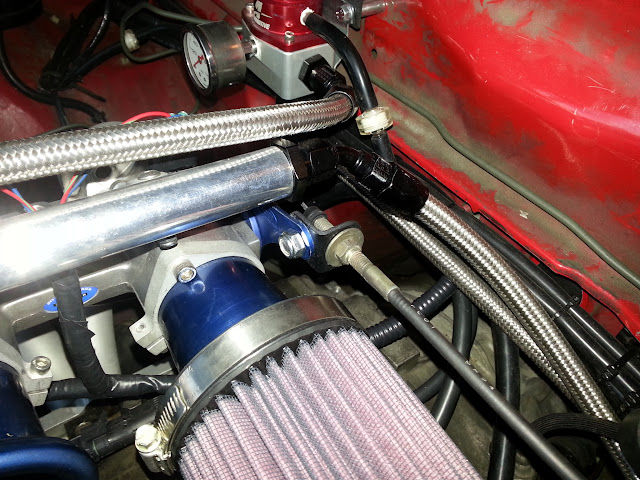
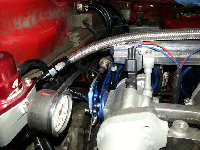
I'm running out of things to do while I wait for the remaining electrical stuff. Just about everything else requires the dummy engine to be removed. Over the weekend I rigged up the stock throttle cable to the ITB, which was more work than anticipated. I ended up having to modify the cable guide arm and cam a little to accept the stock wire. I also made a little bracket out of my favority 1/8" flat stock:

20120916_194545.jpg


20120916_194616.jpg


I still need to modify my bracket a little to make it so I can remove the cable without pulling everything apart. I also really want to get rid of the blue now but I really don't want to have to sand down and polish everything. Is there a way to remove anodized coating chemically?

The biggest difficulty was getting the range of motion of the pedal to match the TB. Unmodified pedal to the floor = ~75% open. After "playing" with the pedal assembly for a bit I got everything to work out. The only thing I don't like if the spring on the TB is a lot weaker than the spring on the stock TB so the pedal is really soft. If anyone has a suggestion for increasing force I'm all ears.

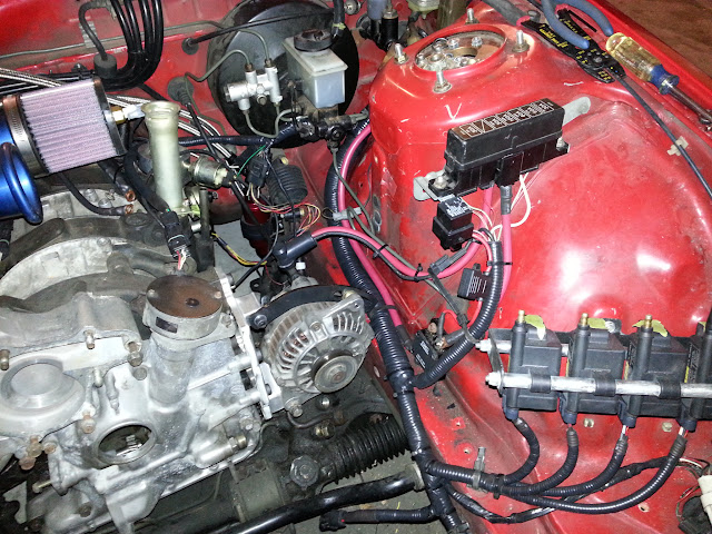
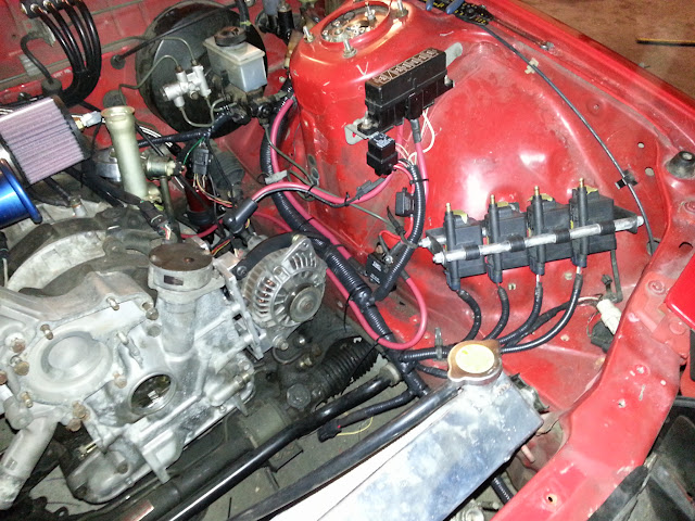
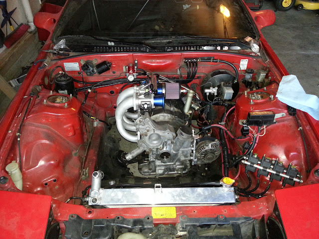
Finally, here's another shot of the engine bay in its current state:

20120916_194735.jpg
 
For some reason oven cleaner comes to mind for removing the anodizing. Not sure why though.
 
For some reason oven cleaner comes to mind for removing the anodizing. Not sure why though.

Oven cleaner works great to removing anodizing, I used it on all my fittings and any thing else that was anodized. you just have a minor polishing to do after the chemical bath.
 
Last edited:
I have no idea how or why that tidbit was in the memory bank. Obviously the malted hops and bong resin haven't killed all the brain cells.
 
Yep, they said oven cleaner as well. I guess it depends on what kind of finish you're going for how rough of an agent you could use.

http://www.finishing.com/2000-2199/2076.shtml

As far as adjusting the pedal resistance, I'm not sure how it ties into the cable, but what if you changed the mounting point on the pedal to lessen the mechanical advantage and in turn increase the effort?
 
For some reason oven cleaner comes to mind for removing the anodizing. Not sure why though.

Oven cleaner works great to removing anodizing, I used it on all my fittings and any thing else that was anodized. you just have a minor polishing to do after the chemical bath.

Yep, they said oven cleaner as well. I guess it depends on what kind of finish you're going for how rough of an agent you could use.

http://www.finishing.com/2000-2199/2076.shtml

Thanks guys. I've been looking into it and apparently sodium hydroxide (NaOH), also known as lye, is what does the trick. Apparently it's the main agent in oven cleaner and drain cleaner, which are two of the most common chemicals I've read being used. What amout of polishing are we talking? While I really don't care about the finish (as long as it's even) on the cable hardware I really don't want a rough finish in the ram tubes.

As far as adjusting the pedal resistance, I'm not sure how it ties into the cable, but what if you changed the mounting point on the pedal to lessen the mechanical advantage and in turn increase the effort?
That would work in theory but would require a ton of work for something that's not technically "broken." Both the pedal and TB springs are the "torsion" type and while I'm sure there are commercially available springs of the same kind that are stiffer, it'd would probably involve a lot of trial and error to get the right one. The solution should really lie in stiffening up the TB spring but it looks like be a specialized design.
 
Back