
Wrapped up my gauge installation. Here are some pictures of key points for me. I'm a decent shade tree mechanic and avvid DIY guy around the house, but hadn't ever done any wiring on a car before. I also never had a reason to dive into wiring diagrams, and this project gave me a good reason, so I added a few tips in case anyone else is fuzzy on how to read a wiring diagram. Enjoy.
Not affiliated w/any product or company whose product is about to be shown.
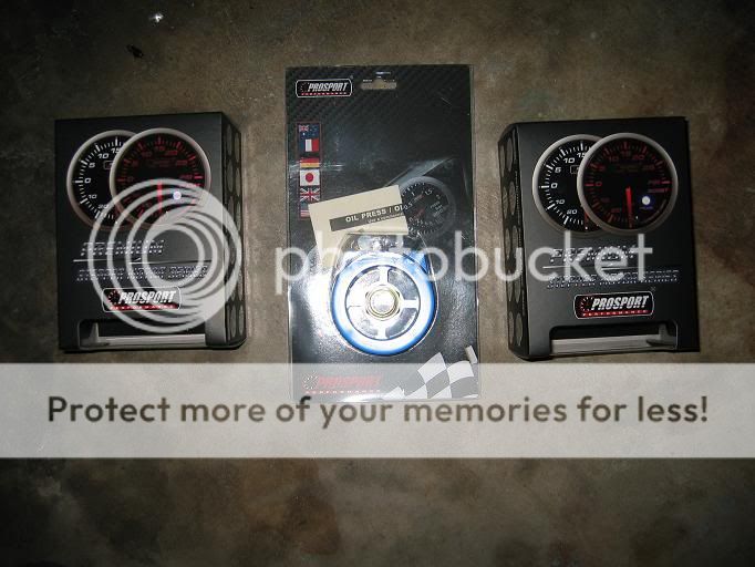
Starting off w/the gauges & adapter:
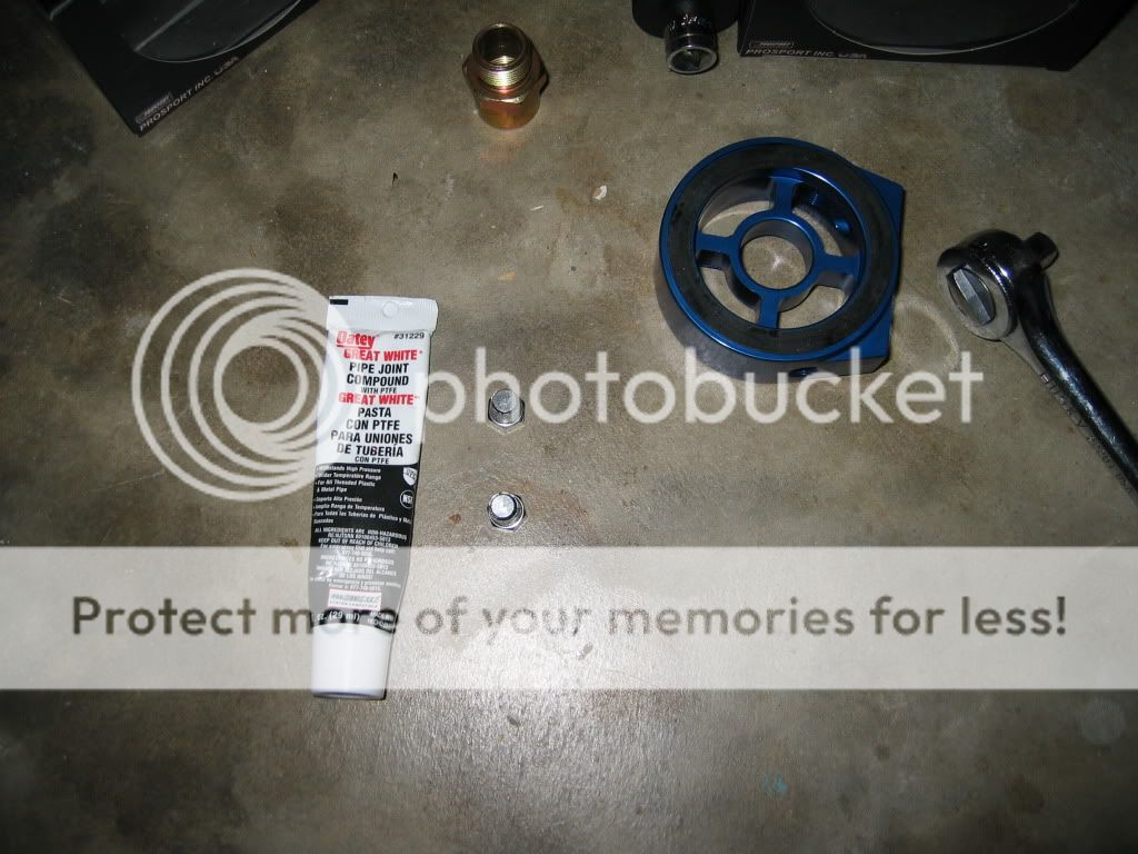
Next, prep the adapter, sensors, and plugs. The adapter I purchased has 4 holes for sensors and comes with 4 plugs. I'm only using two holes. The thread sealant pictured is Oatey Great White #31229 It can be used on oils and is good up to 10,000 PSI on liquids from -50 to +500F. Can be purchased from your neighborhood HW store, usually in the plumbing section.
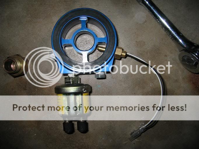
Next, the completed prepped adapter & sensors. I chose to install the sensors in these locations based on how the test-fit looked:
The next thing I did was get some 18 gauge wire in various colors, along with bullet connectors and ring terminals, and go to town on cutting about 6' ft lengths with the proper connectors. There are so many ways to do this; it just depends on how you want it. Another thing I did was put a ring terminal on the Oil Temp sensor Ground wire (black) and connect it to the Oil Pressure sensor Ground Terminal (creating a little daisy chain), then I ran a another longer Ground Wire from the Oil Pressure Ground Terminal to my grounding point on the car near the battery. It goes like this:
Oil Temp Ground --> ring terminal to Oil Pressure Ground Terminal -> second ring terminal to 6'-ish wire connecting to the car's ground
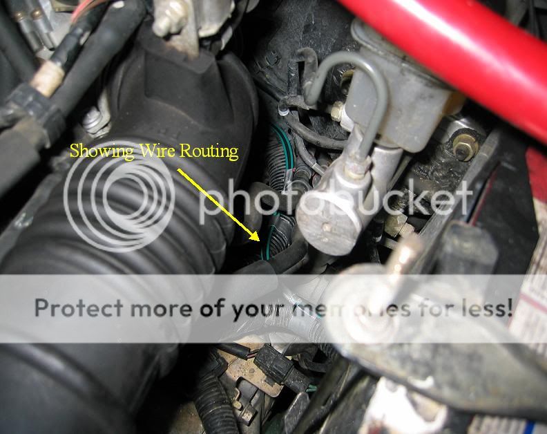
Next just shows how I routed the wires. Good ol' duct tape...I'm sure there is a specific product I should have used here instead.
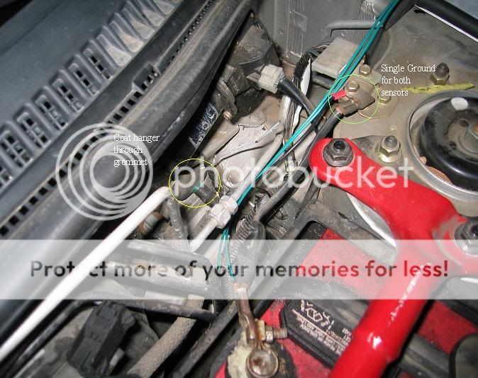
The next picture shows a coat hangar poking through the firewall grommet, as well as my chosen ground location, connected with another ring terminal.
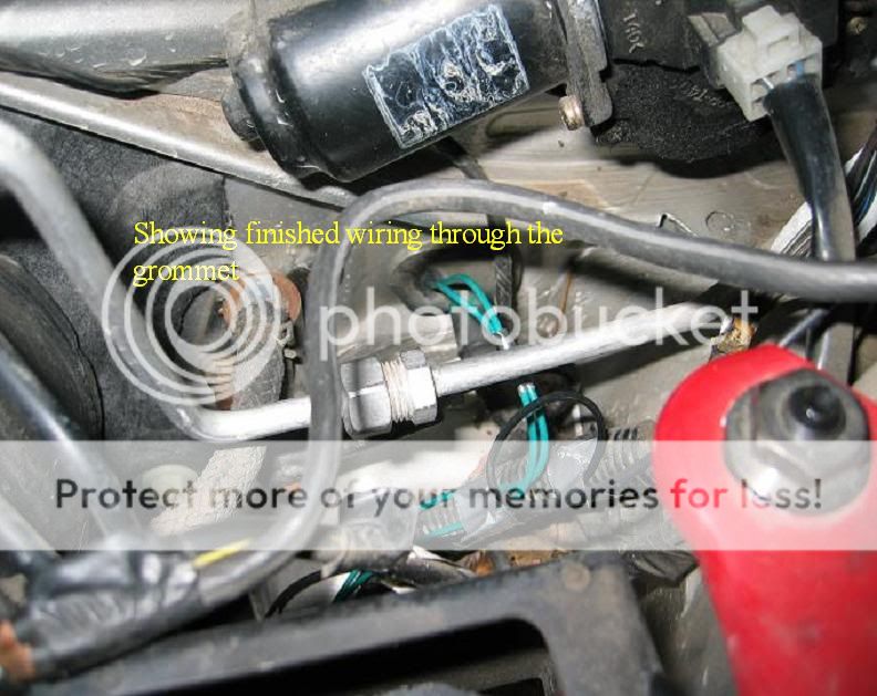
In the next picture, you can see that I've fished both sender wires through
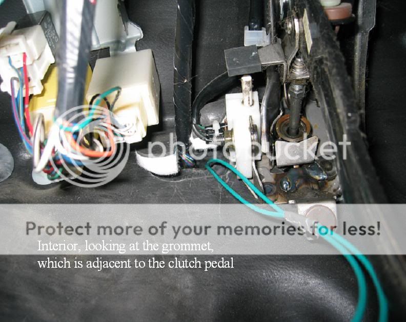
Next, a view from inside the cabin, under the dash at the spot where the wires come inside
Now that the sensor wiring is more or less complete, it's time to move on to the gauge wiring. This is all about trying to find where to tap into for power, ground, and lighting control. I have the gauges that have the optional control wire to change to/from white and amber. This is where the wiring diagram comes into play. I researched on this forum about which wires to grab, and there is a fair amount of conflicting or incomplete information, which is why I sat down and had a look at the wiring diagram.
Since my gauges don't have any need for constant power (the gauges have no alarm settings or other settings that need constant battery power), I can get by with just providing switched power. Because I know I'll be adding more gauges later (hopefully when going turbo), I wanted to start off on a fused supply that didn't have much else on it, which for me, meant the cigarette lighter circuit.
I also wanted to use the lighting control wire on the gauge to turn it amber when my headlights were on, so I had to also find the headlight switch control wire.
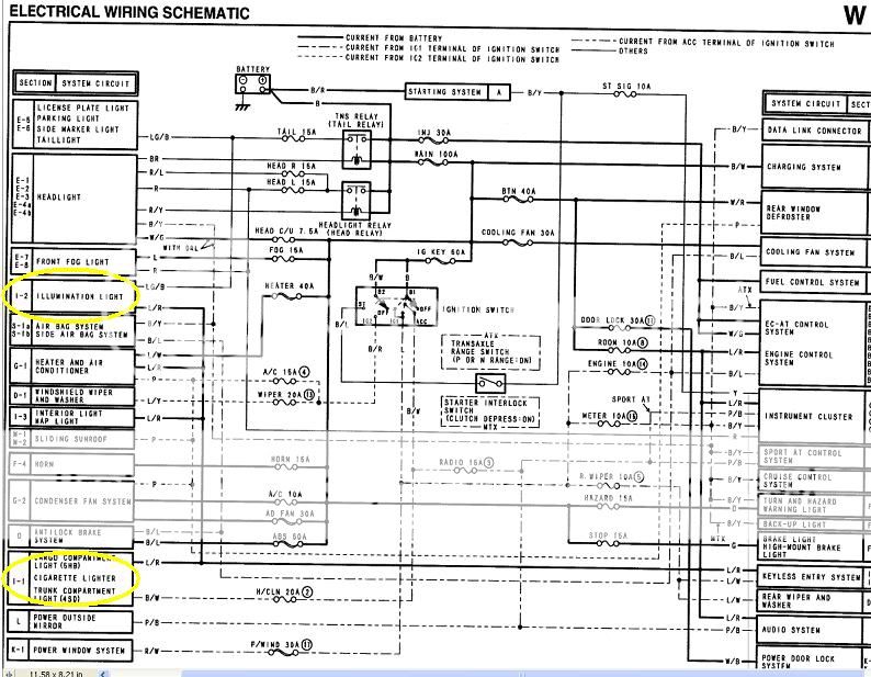
Finding the Cigarette lighter circuit on the diagram is easy - it has its own section. Finding the headlight switch is easy if you know that it attaches to the factory audio harness, and this can seen in the 'Illumination' section of the wiring diagram. Incidentally, the Illumination section of the wiring diagram also includes details on the dimmer switch, which I tired wiring into the control wire on the gauge and didn't achieve the desired dimming behavior. No biggy, I think I like it changing colors from white to amber with the headlight switch anyway.
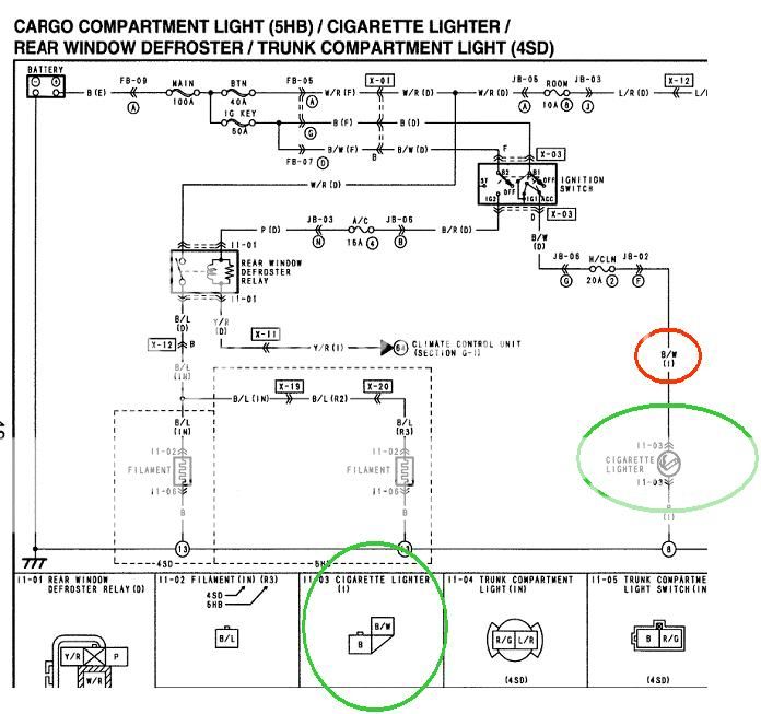
Moving right along, again, the two sections of interest are the Cigarette Lighter and Illumination section, which can be seen from the top-level schematic in the wiring diagram, circled both in Yellow.
Now is a good time to mention the Color Code table, because we'll use that to figure out what are the physical colors of the wires we care care about:
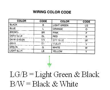
Let's start with the Cigarette Lighter section since it provides switched power (is off when the car is off, and turns on when the key is either in Acc or On). Circled in Green is both the schematic picture of the lighter and the diagram of the actual connector that attaches to the lighter. Circled in Red are the letters 'B/W', which stand for Black & White based on the color code chart. Following the line up labeled B/W up and to the left, it connects to a 20A fuse, and then connects to the Ignition Switch at the Acc/Ign terminals. This tells us that the B/W wire is definitely a switched +12V supply. Meaning, when we want to tap the Black & White wire at the cigarette lighter for power.
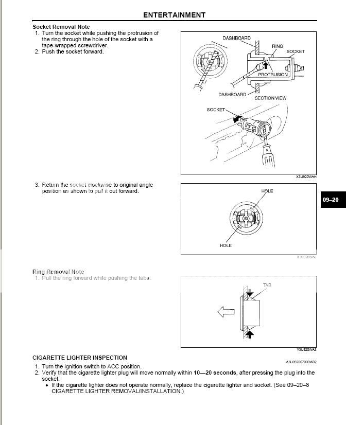
To do all of the gauge wiring, I removed the console, glove box, radio, HVAC controls + panel surround. Removing the cigarette lighter is easy, but does require pushing in a small tab w/a flat head screwdriver whilst pulling it out. See pg 9-20-8 of the Service Manual, also pictured below:
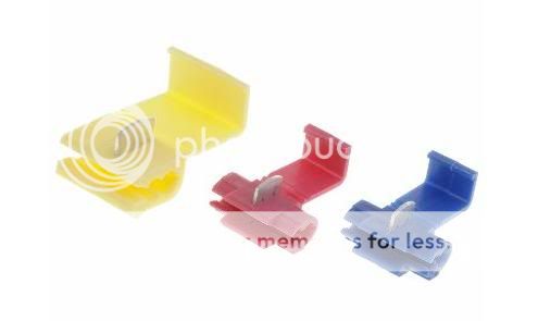
I then used a Quick Splice Terminal to easily tap into the black & white 12V power wire connecting to the cigarette lighter. Make sure to do it high enough on the line so that it doesn't interfere with things when you reassemble the lighter & other components:
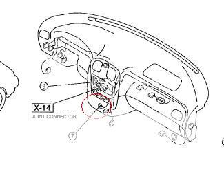
Next, for Ground, there is a good location under the climate control area, viewable when you're head is under the steering wheel, looking into the area behind the radio/climate controls. I combined the ground wires and used a ring terminal to connect to this ground point. My Wiring Diagram lists ground points on the car on pg 7, snippet below, circled in Red. I believe it's maybe an 8mm or 10mm hex bolt.
Now that power and ground are complete, it's time to do the lighting control. I chose to tap the headlight switch wire, which connects to the audio harness, which you can see in the Illumination section of the Wiring Diagram, pictured below. Circled in Red is the audio unit light, a line with label "LG/B", and one spot on the audio harness connector also labeled "LG/B". Referring to the color code chart, LG/B = Light Green & Black. So, now we know that the wire we want is Light Green & Black and we know exactly where it should connect to on the audio harness. Knowing where it goes on the audio harness helps to verify that the correct wire has actually been chosen. As before, grab a quick splice terminal and connect up your wires.
Also note that if you wanted to try the dimmer wire, it too is shown in the picture above. The 'Panel Light Control Switch' is the actual dimmer, and the W/L wire is the output of the dimmer switch. The W/L wire is also on the audio harness connector, right next to the headlight switch wire
For mounting the gauges, I went the DIN Panel Mount way since I have an aftermarket single DIN radio. I also have one gauge blank since I have three spots in the panel and am only using two gauges. One thing to note is that the panel fits very loosely and I need to line it with felt or weatherstripping b/c the vibration is a bit annoying.
So finally, the finished product:
Gauges off

Gauges On Daylight

Gauges On Nighttime

Gauges On Nighttime closeup

Not affiliated w/any product or company whose product is about to be shown.
Starting off w/the gauges & adapter:
Next, prep the adapter, sensors, and plugs. The adapter I purchased has 4 holes for sensors and comes with 4 plugs. I'm only using two holes. The thread sealant pictured is Oatey Great White #31229 It can be used on oils and is good up to 10,000 PSI on liquids from -50 to +500F. Can be purchased from your neighborhood HW store, usually in the plumbing section.
Next, the completed prepped adapter & sensors. I chose to install the sensors in these locations based on how the test-fit looked:
The next thing I did was get some 18 gauge wire in various colors, along with bullet connectors and ring terminals, and go to town on cutting about 6' ft lengths with the proper connectors. There are so many ways to do this; it just depends on how you want it. Another thing I did was put a ring terminal on the Oil Temp sensor Ground wire (black) and connect it to the Oil Pressure sensor Ground Terminal (creating a little daisy chain), then I ran a another longer Ground Wire from the Oil Pressure Ground Terminal to my grounding point on the car near the battery. It goes like this:
Oil Temp Ground --> ring terminal to Oil Pressure Ground Terminal -> second ring terminal to 6'-ish wire connecting to the car's ground
Next just shows how I routed the wires. Good ol' duct tape...I'm sure there is a specific product I should have used here instead.
The next picture shows a coat hangar poking through the firewall grommet, as well as my chosen ground location, connected with another ring terminal.
In the next picture, you can see that I've fished both sender wires through
Next, a view from inside the cabin, under the dash at the spot where the wires come inside
Now that the sensor wiring is more or less complete, it's time to move on to the gauge wiring. This is all about trying to find where to tap into for power, ground, and lighting control. I have the gauges that have the optional control wire to change to/from white and amber. This is where the wiring diagram comes into play. I researched on this forum about which wires to grab, and there is a fair amount of conflicting or incomplete information, which is why I sat down and had a look at the wiring diagram.
Since my gauges don't have any need for constant power (the gauges have no alarm settings or other settings that need constant battery power), I can get by with just providing switched power. Because I know I'll be adding more gauges later (hopefully when going turbo), I wanted to start off on a fused supply that didn't have much else on it, which for me, meant the cigarette lighter circuit.
I also wanted to use the lighting control wire on the gauge to turn it amber when my headlights were on, so I had to also find the headlight switch control wire.
Finding the Cigarette lighter circuit on the diagram is easy - it has its own section. Finding the headlight switch is easy if you know that it attaches to the factory audio harness, and this can seen in the 'Illumination' section of the wiring diagram. Incidentally, the Illumination section of the wiring diagram also includes details on the dimmer switch, which I tired wiring into the control wire on the gauge and didn't achieve the desired dimming behavior. No biggy, I think I like it changing colors from white to amber with the headlight switch anyway.
Moving right along, again, the two sections of interest are the Cigarette Lighter and Illumination section, which can be seen from the top-level schematic in the wiring diagram, circled both in Yellow.
Now is a good time to mention the Color Code table, because we'll use that to figure out what are the physical colors of the wires we care care about:
Let's start with the Cigarette Lighter section since it provides switched power (is off when the car is off, and turns on when the key is either in Acc or On). Circled in Green is both the schematic picture of the lighter and the diagram of the actual connector that attaches to the lighter. Circled in Red are the letters 'B/W', which stand for Black & White based on the color code chart. Following the line up labeled B/W up and to the left, it connects to a 20A fuse, and then connects to the Ignition Switch at the Acc/Ign terminals. This tells us that the B/W wire is definitely a switched +12V supply. Meaning, when we want to tap the Black & White wire at the cigarette lighter for power.
To do all of the gauge wiring, I removed the console, glove box, radio, HVAC controls + panel surround. Removing the cigarette lighter is easy, but does require pushing in a small tab w/a flat head screwdriver whilst pulling it out. See pg 9-20-8 of the Service Manual, also pictured below:
I then used a Quick Splice Terminal to easily tap into the black & white 12V power wire connecting to the cigarette lighter. Make sure to do it high enough on the line so that it doesn't interfere with things when you reassemble the lighter & other components:
Next, for Ground, there is a good location under the climate control area, viewable when you're head is under the steering wheel, looking into the area behind the radio/climate controls. I combined the ground wires and used a ring terminal to connect to this ground point. My Wiring Diagram lists ground points on the car on pg 7, snippet below, circled in Red. I believe it's maybe an 8mm or 10mm hex bolt.
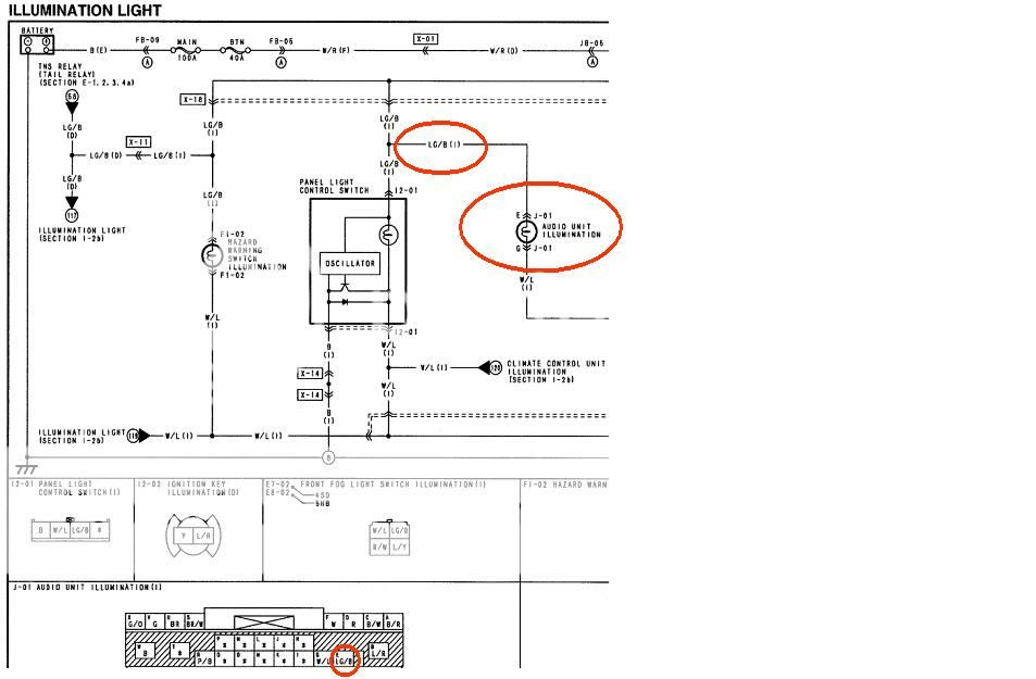
Now that power and ground are complete, it's time to do the lighting control. I chose to tap the headlight switch wire, which connects to the audio harness, which you can see in the Illumination section of the Wiring Diagram, pictured below. Circled in Red is the audio unit light, a line with label "LG/B", and one spot on the audio harness connector also labeled "LG/B". Referring to the color code chart, LG/B = Light Green & Black. So, now we know that the wire we want is Light Green & Black and we know exactly where it should connect to on the audio harness. Knowing where it goes on the audio harness helps to verify that the correct wire has actually been chosen. As before, grab a quick splice terminal and connect up your wires.
Also note that if you wanted to try the dimmer wire, it too is shown in the picture above. The 'Panel Light Control Switch' is the actual dimmer, and the W/L wire is the output of the dimmer switch. The W/L wire is also on the audio harness connector, right next to the headlight switch wire
For mounting the gauges, I went the DIN Panel Mount way since I have an aftermarket single DIN radio. I also have one gauge blank since I have three spots in the panel and am only using two gauges. One thing to note is that the panel fits very loosely and I need to line it with felt or weatherstripping b/c the vibration is a bit annoying.
So finally, the finished product:
Gauges off
Gauges On Daylight
Gauges On Nighttime
Gauges On Nighttime closeup