I ordered all the parts from partsexpress and hope to do this mod within the next couple weeks. I'll post back how it goes. I hope it works with my amp since it was kind of cheap, Alpine V-Power MRP-F200. All I was able to find about the input voltage was this, "[FONT=Arial, Helvetica]gain control allows you to match the output level of the head unit, 200mV to 4V."[/FONT]

You are using an out of date browser. It may not display this or other websites correctly.
You should upgrade or use an alternative browser.
You should upgrade or use an alternative browser.
How-To: Stock head unit with RCA outs (P5)
- Thread starter Antoine
- Start date
tschanrm said:Oh, ok, I thought you wanted to boost the signal from inside the headunit. That sounds like a nice, easy one to install, and much cheaper than the 10v competition driver they sell.
Also, some good news, I think I found a way to bypass the loudness feature! I thought the loudness components were inside the chip, but it seems the boosted frequencies are done via external resistors and capacitors. I may be taking my headunit apart this weekend and finding out, stay tuned!
Here are some more line drivers. http://www.cardomain.com/item/PERPLD10
this unit says it boosts the output to 10V RMS, seems almost too good for only $29.95.
Another http://www.cardomain.com/item/PIELD1
a bit more expensive at $30.95 and it doesn't state what its output is.
So would either of these be enough to boost the system to be good for any amp?
Also, any of you electrical savy people plan on adding RCA's to other peoples HU's for a fee???
Last edited:
I think tschanrm isn't in the US so shipping would be price for him to do it. But I'd be willing to help you out. Just keep in mind that shipping the unit both ways + shipping the supplies will cost a little.
Maybe if we get a bunch of people that want it done I can sit down one afternoon and pump out a bunch of them.
Either of those line-drivers should work but sometimes they introduce whine or noise into the signal. It's worth a shot though, and you can always return it.
Maybe if we get a bunch of people that want it done I can sit down one afternoon and pump out a bunch of them.
Either of those line-drivers should work but sometimes they introduce whine or noise into the signal. It's worth a shot though, and you can always return it.
julester23
Member
So I just put in a little old rockford fosgate four channel (200aIV or 200a4) with the after market stereo that came in my car, and everything works fine. Now I want to swap back to the stock radio with the RCA out mod. Is there any way to make sure the amp is only on when the stock radio is on? The "Pin 10: Pink / Black - Switched power" will turn on as soon as the key is in ACC mode. I'm not sure this is worth the effort, but it would help complete the ultimate stock radio mod. I'm guessing some sort of pcb trace would need a buffer or buffer and mosfet to drive the 200mA or whatever the amp sucks up.
Great work btw.
Great work btw.
Last edited:
Hmm, tschanrm might be able to find something inside the unit that would give you a remote turn on. I just wire it right into the fuse for the radio and other accessories. That means it is always on when the car is on...but how often do you have the radio off while driving? The amp doesn't draw very much current when it isn't playing any sound anyway.
I was gonna ask the same thing. I used to have my amp on whenever the car was on but when I would turn the HU on/off the speakers would pop. I switched to a current sensing thingy connected to a speaker wire so when the HU sends out sound it turns the amp on. I am assuming that after the RCA mod the HU will still send a signal through the speaker line, otherwise I'll have to come up with something else to turn the amp on/off.
The current sensing thing added some alternator noise though. I think its because I used the HU power/ground for it. When I do the RCA mod (hopefully this weekend) I'll ground it to the car and hopefully that will get rid of it. But I think modding something inside the HU to turn the amp on would have less chance of adding noise right?
The current sensing thing added some alternator noise though. I think its because I used the HU power/ground for it. When I do the RCA mod (hopefully this weekend) I'll ground it to the car and hopefully that will get rid of it. But I think modding something inside the HU to turn the amp on would have less chance of adding noise right?
I tried this today and it didn't go well. I ended up quiting before soldering anything to the PCB. Your HU PCB has nice holes to stick the wires through. Mine did not, all the holes were filled with solder. While trying to remove the solder I think I broke a trace. I have no solder removing tool so I was trying to get as much as I could out with just the iron and then trying to poke a solid wire through while heating it up with the soldering iron. Anyway I scraped off the nice little gold looking ring around the hole, along with a little bit of it that went away from the hole. This was for the front left channel, it came off on the side with all the components. The trace goes under the chip there so I don't know what to do now. Then I was trying to get the solder out of the rear left and the same thing happened, although it was on the backside where there aren't any components, so that might be easy to fix.
I don't know if I should just pick up a used stock HU and try again, hoping to get one without solder in the holes. Or if I should try and fix it. I have seen those circuit writer pens, could I use that to try and fix the traces I messed up?
I don't know if I should just pick up a used stock HU and try again, hoping to get one without solder in the holes. Or if I should try and fix it. I have seen those circuit writer pens, could I use that to try and fix the traces I messed up?
Last edited:
julester23
Member
I've done the heat and force components into holes many times - never works perfectly, but always tempting to try.
I am sure you can fix this...don't bother getting another. There are two ways to remove solder that I know...one is with a solder wick, and the other is with a solder pump. I recommend you just try and get one of those. Lookup "desolder" on google for details.
If you don't want to get one, you could try blowing the hot solder through the hole (while the iron is keeping it hot). - wear glasses! - I don't think you need those rings you removed - it's just a drilled solder pad if I'm reading your description correctly. if you removed part of a surface trace, you can always use a scrap of metal wire to reconnect (might be best to pin it down while you solder).
Yeah, I'm gonna try to fix it tomorrow. I was just getting frustrated. At least I stopped working on it before I screwed it up too badly.
I actually have de-soldering wick, but I have never had any luck with it. I was using the blowing method, but I couldn't get the last bit of solder out. Thats when I started being retarded and messing stuff up lol
I actually have de-soldering wick, but I have never had any luck with it. I was using the blowing method, but I couldn't get the last bit of solder out. Thats when I started being retarded and messing stuff up lol
julester23
Member
tschanrm, or chuyler1, I have four questions:
1) Why is polarized electrolytic type capacitor suggested over non polarized?
2) My amp (RF 200a4) has "sensitivity" between 250mV and 4V and a 20kohm input impedance. I calculate a -3dB at 20Hz capacitor value of 0.96uF. Is this correct? What do you think of the "sensitivity"? Is it sufficient without needing a line driver?
3) You mention choosing your cap based on reducing DC offset. How does the cap value affect DC offset? I thought any size cap will block DC.
4) Why the 50V rating? what kind of DC offset are we talking? i'd measure it, but i don't have a scope. I would prefer to use smaller rated caps due to size constraints.
Last edited:
The caps tschanrm suggested fit perfectly fine between the cage and the board. Tschanrm will have to answer your other questions. He seems to know what he is talking about so I just followed suit.
I just picked up a new stock unit from a board member for $15. It has a broken 6-disc changer but I'm going to play around with it. Worst case scenario, I'll install the RCA pre-outs and sell it to a board member who can just replace the disc unit with their own.
I just picked up a new stock unit from a board member for $15. It has a broken 6-disc changer but I'm going to play around with it. Worst case scenario, I'll install the RCA pre-outs and sell it to a board member who can just replace the disc unit with their own.
So I tried to salvage my HU. I ended up getting both rear channels working but I couldn't get the front. Also the right channel was much louder than the left channel. I figured I just screwed something up.
I went ahead and got a 2nd HU. I finished the RCA and loudness mod just now. To test it I connected it to an old PC power supply I had sitting around and an old PC speaker. Everything worked great except the right channels are much louder than the left channels again. This is for both front and rear. I don't know what I'm doing wrong for this to happen on the old HU and this new one. I checked the instructions/pictures and everything looks right. At this point I am lost. I'll take it apart again and get pictures tomorrow. I wish I wouldn't have done the loudness mod at the same time both times, then I would at least know if the problem was with the RCA mod or the loudness mod.
I did notice something on the first steps of the how-to, you don't have to remove the screws off the top of the CD player module. My single disc module didn't even have screws on the top, only my 6 disc one does. Either way you can remove the module without taking that top plate off. There is a slot on each side where you stick a flat head screw driver and pry up. The picture on the top of the module actually shows it.
I checked that and double checked all my connections again and everything looks right.
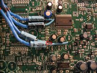
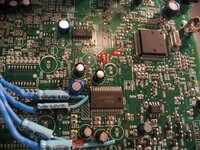
I did notice I have some components(resistors and/or capacitors) on both my boards that you and tschanrm do not. I circled some of them in the pics. Maybe that difference is what is causing my problem.
I had more pics but they came out blurry, here are the two good ones.
I did notice I have some components(resistors and/or capacitors) on both my boards that you and tschanrm do not. I circled some of them in the pics. Maybe that difference is what is causing my problem.
I had more pics but they came out blurry, here are the two good ones.
Attachments
Has anybody else tried the mod to remove the loudness feature? I think it is the reason my right/left channels are at such different volumes. I put the CD player in my car tonight to see how bad it really was. To make it even I have to adjust the balance so that it is 1 away from all the way left. I've actually been thinking about just buying an aftermarket HU now. Or maybe picking one up until I get my stock HU working correctly again. I could get one from Wal-Mart and just return it when I'm done with it ")
julester23 said:So I just put in a little old rockford fosgate four channel (200aIV or 200a4) with the after market stereo that came in my car, and everything works fine. Now I want to swap back to the stock radio with the RCA out mod. Is there any way to make sure the amp is only on when the stock radio is on? The "Pin 10: Pink / Black - Switched power" will turn on as soon as the key is in ACC mode. I'm not sure this is worth the effort, but it would help complete the ultimate stock radio mod. I'm guessing some sort of pcb trace would need a buffer or buffer and mosfet to drive the 200mA or whatever the amp sucks up.
Great work btw.
I spliced into one of the wires on the radio harness to get my 12 V accessory switch. There are no clear markings on the inside of the unit for the 12v switched. Plus, you stand a greater chance of shorting something out by trying to splice into 12 internally.
Also, any of you electrical savy people plan on adding RCA's to other peoples HU's for a fee???
If I had time to do the mods I would. Right now work has me in overdrive....
1.) No real reason, just so people wouldn't have to ask which one to get. Personally I think it is easier to find a wider variety of polarized electrolytic capacitor values.1) Why is polarized electrolytic type capacitor suggested over non polarized?
2) My amp (RF 200a4) has "sensitivity" between 250mV and 4V and a 20kohm input impedance. I calculate a -3dB at 20Hz capacitor value of 0.96uF. Is this correct? What do you think of the "sensitivity"? Is it sufficient without needing a line driver?
3) You mention choosing your cap based on reducing DC offset. How does the cap value affect DC offset? I thought any size cap will block DC.
4) Why the 50V rating? what kind of DC offset are we talking? i'd measure it, but i don't have a scope. I would prefer to use smaller rated caps due to size constraints.
2.) Pretty sure your calculation is correct. 4v sensitivity probably means you will need a line driver.
3.) If you go too low of a farad value, it is my understanding that you will not sufficiently block all DC offset. I forget where this scenario is the case, but I'm pretty sure it exists. I think I meant to say choosing a cap based on impedence for that part.
4.) I chose 50v because I never took the time to trace back where the amp chip hooked up throughout the entire unit. The amp chip has a supply voltage of 25v, with a 65v peak surge. I forget what dc offset was when I initially checked it, but it was high,somewhere in the V range (not mv range). The volume chip has a max supply voltage of 10v. You could probably use a 16v or 25v and be fine.
As to using a smaller volt rating to put in a larger farad cap, testing showed little improvement in frequency response. I was originally using .96uf 25v caps, but when testing I saw less than a .5db frequency response difference at the low end between the .96uf/25v and the .47uf/50v. Because of this, and the fact that I didn't want to trace the entire amp section, I chose the 50v.
Has anybody else tried the mod to remove the loudness feature? I think it is the reason my right/left channels are at such different volumes. I put the CD player in my car tonight to see how bad it really was. To make it even I have to adjust the balance so that it is 1 away from all the way left.
Sounds like you didn't bridge one of the smd pads. You need to bridge the smd pads so you can have a half-voltage reference going to the loudness pins. There is a resistor for each loudness pin that connects to the half-volt reference. Without this voltage, the volume ramps up to full volume at what should be only half volume.
As an observation, removing the loudness countour really brought back sound quality at lower listening levels(less than half volume). I always found the lower listening levels tinny sounding, now it is natural and even.
Last edited:
you are talking about the thing that you put your wires into it and it comes out RCA..? ya seriously what is the + of doing this whole mod instead of buying that line converter?
i have a kenwood 928 that worth like 500 and im thinking about putting the stock HU in my car. id like to go back double din.
if the pros are interresting ill ship the radio to somebody to have the electrical job done. else ill get a line converter...
i have a kenwood 928 that worth like 500 and im thinking about putting the stock HU in my car. id like to go back double din.
if the pros are interresting ill ship the radio to somebody to have the electrical job done. else ill get a line converter...
Similar threads
- Replies
- 2
- Views
- 2K