
You are using an out of date browser. It may not display this or other websites correctly.
You should upgrade or use an alternative browser.
You should upgrade or use an alternative browser.
Wiring / Electrical Diagram
- Thread starter RobertWK
- Start date
flatlander937
Member
- :
- '11 Mazda2 Sport
Which one(s)? I can get them from work.
flatlander937
Member
- :
- '11 Mazda2 Sport
Printed them out, I'll scan them in or take pics of the prints later tonight or tomorrow.
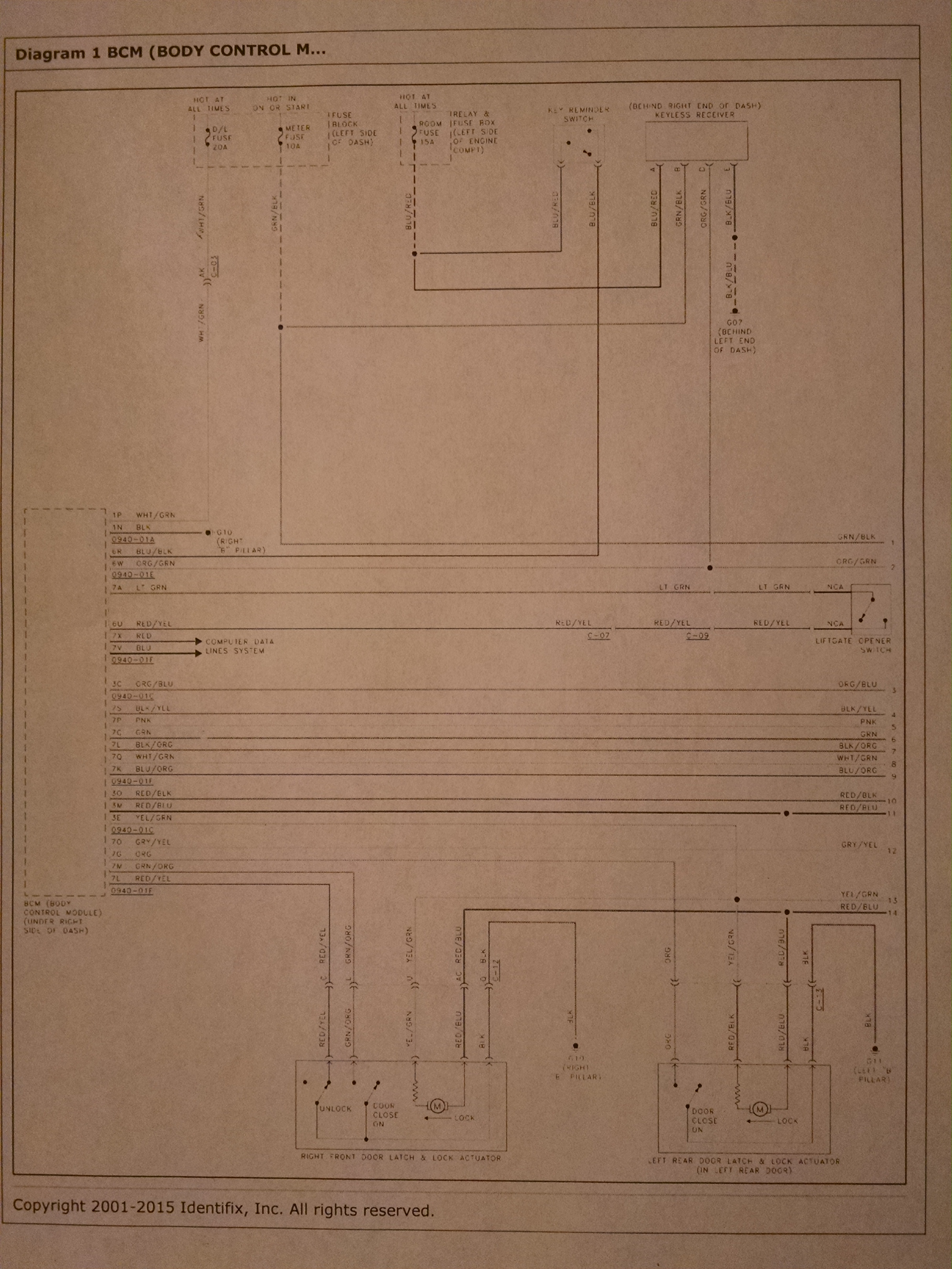
The speedo is all on the CAN bus, signals come from the wheel speed sensors to the BCM, you'd need to make a circuit that converts the AC voltage into something useful to be interpreted, then send a signal to the door lock actuators to lock at a set speed. But you also need to either a) make it so it only locks once or b) utilize the lock switch sense circuit that tells the BCM that it is either locked or unlocked already.
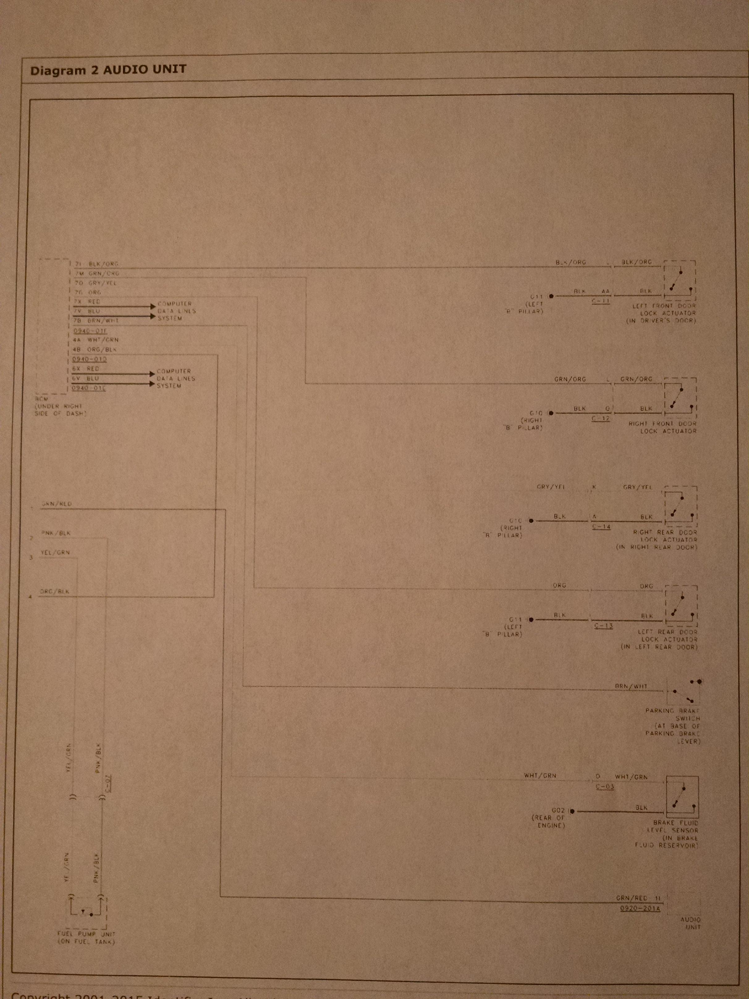
The actuators themselves are just motors that most likely function like all others: ground is supplied on both sides by the BCM, and one switches to +12v to lock or unlock, depending on which of the two wires it powers.
You do NOT want to tap into these wires to switch power on for auto locking... You will short on the BCM or best case blow a fuse.
You want to put a signal on the lock switch side of things(fool the BCM into thinking the center console switch is being pressed one way or the other.
Problem with Mazda diagrams is they're awful. It shows the center switch as a single pole switch, just ground on one side and pink wire to BCM on the other.... But it locks AND unlocks. So either the diagram is wrong or the switch internally has resistor(s) on each part for different resistances for lock and unlock, as a mini CAN bus style, just like how our steering wheel controls work.
(I stumbled on your thread about wanting auto locking and/or unlocking in another section).
The speedo is all on the CAN bus, signals come from the wheel speed sensors to the BCM, you'd need to make a circuit that converts the AC voltage into something useful to be interpreted, then send a signal to the door lock actuators to lock at a set speed. But you also need to either a) make it so it only locks once or b) utilize the lock switch sense circuit that tells the BCM that it is either locked or unlocked already.
The actuators themselves are just motors that most likely function like all others: ground is supplied on both sides by the BCM, and one switches to +12v to lock or unlock, depending on which of the two wires it powers.
You do NOT want to tap into these wires to switch power on for auto locking... You will short on the BCM or best case blow a fuse.
You want to put a signal on the lock switch side of things(fool the BCM into thinking the center console switch is being pressed one way or the other.
Problem with Mazda diagrams is they're awful. It shows the center switch as a single pole switch, just ground on one side and pink wire to BCM on the other.... But it locks AND unlocks. So either the diagram is wrong or the switch internally has resistor(s) on each part for different resistances for lock and unlock, as a mini CAN bus style, just like how our steering wheel controls work.
(I stumbled on your thread about wanting auto locking and/or unlocking in another section).
flatlander937
Member
- :
- '11 Mazda2 Sport
flatlander937
Member
- :
- '11 Mazda2 Sport
One alternative I'd consider is a frequency to voltage converter to use engine RPM(via an ignition coil) to lock the doors. Set it to like 3k rpms, and wire it so once it locks one time, it disables itself. You'd need some kind of delayed relay or something.
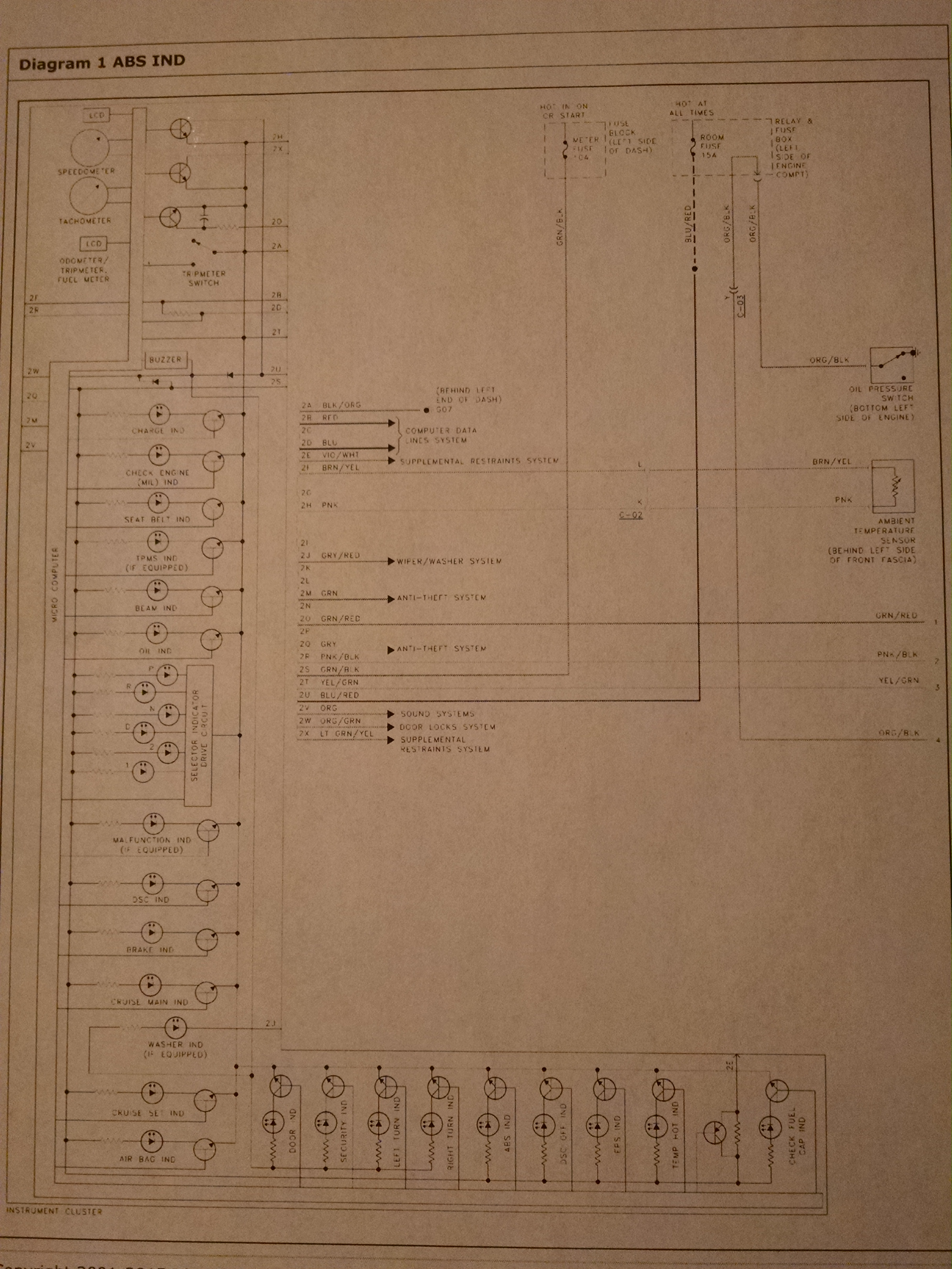
FWIW the ABS runs a self test for the first ignition cycle when you reach 10-15mph.. Could be used possibly? Not sure what gets powered, its likely all internal to the module itself since the solenoids are inside the ABS module.
Only problem is if your ABS engages in normal use your door locks will go nuts even if it were doable
Last edited:
flatlander937
Member
- :
- '11 Mazda2 Sport
flatlander937
Member
- :
- '11 Mazda2 Sport
More info:
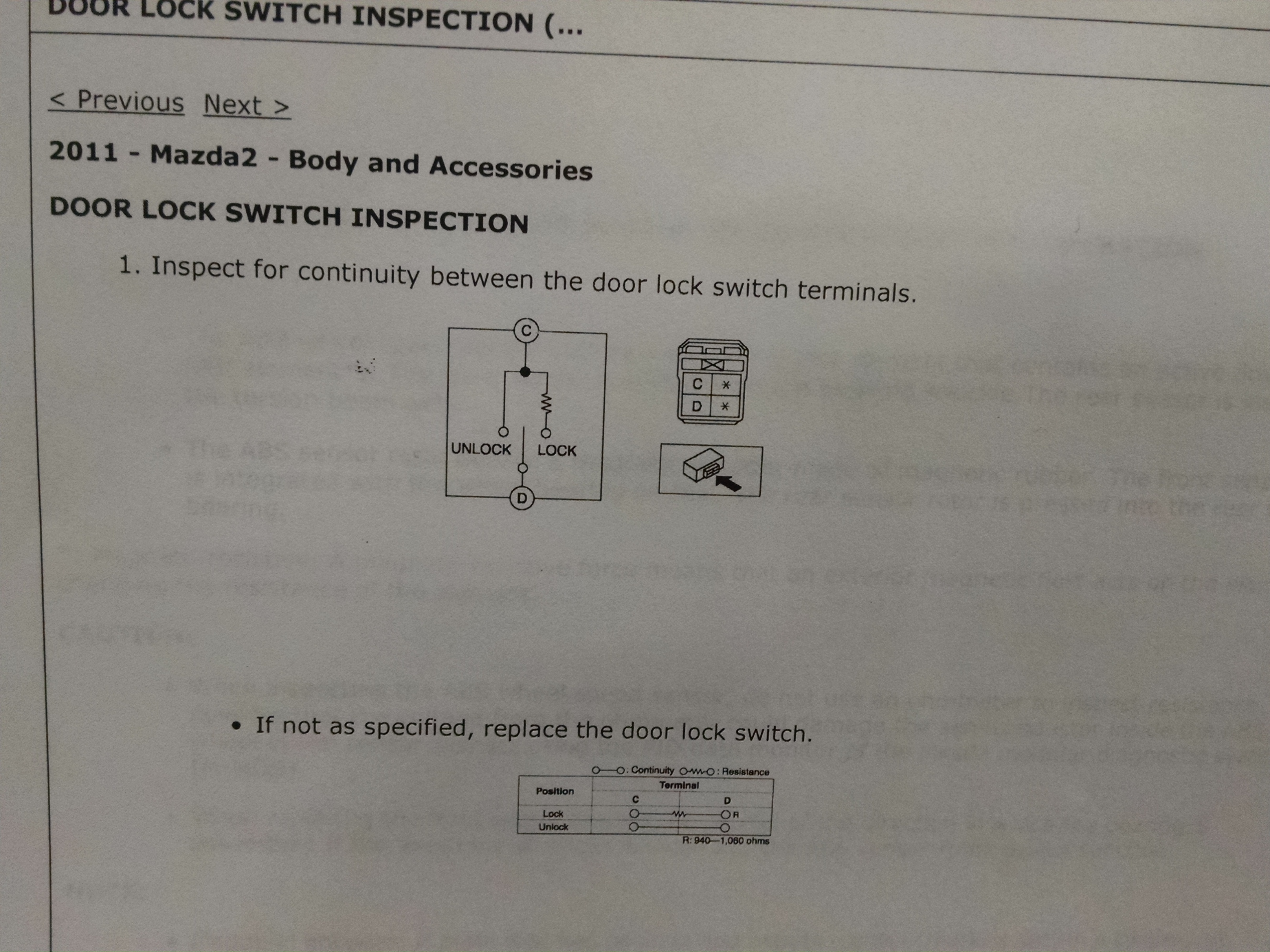
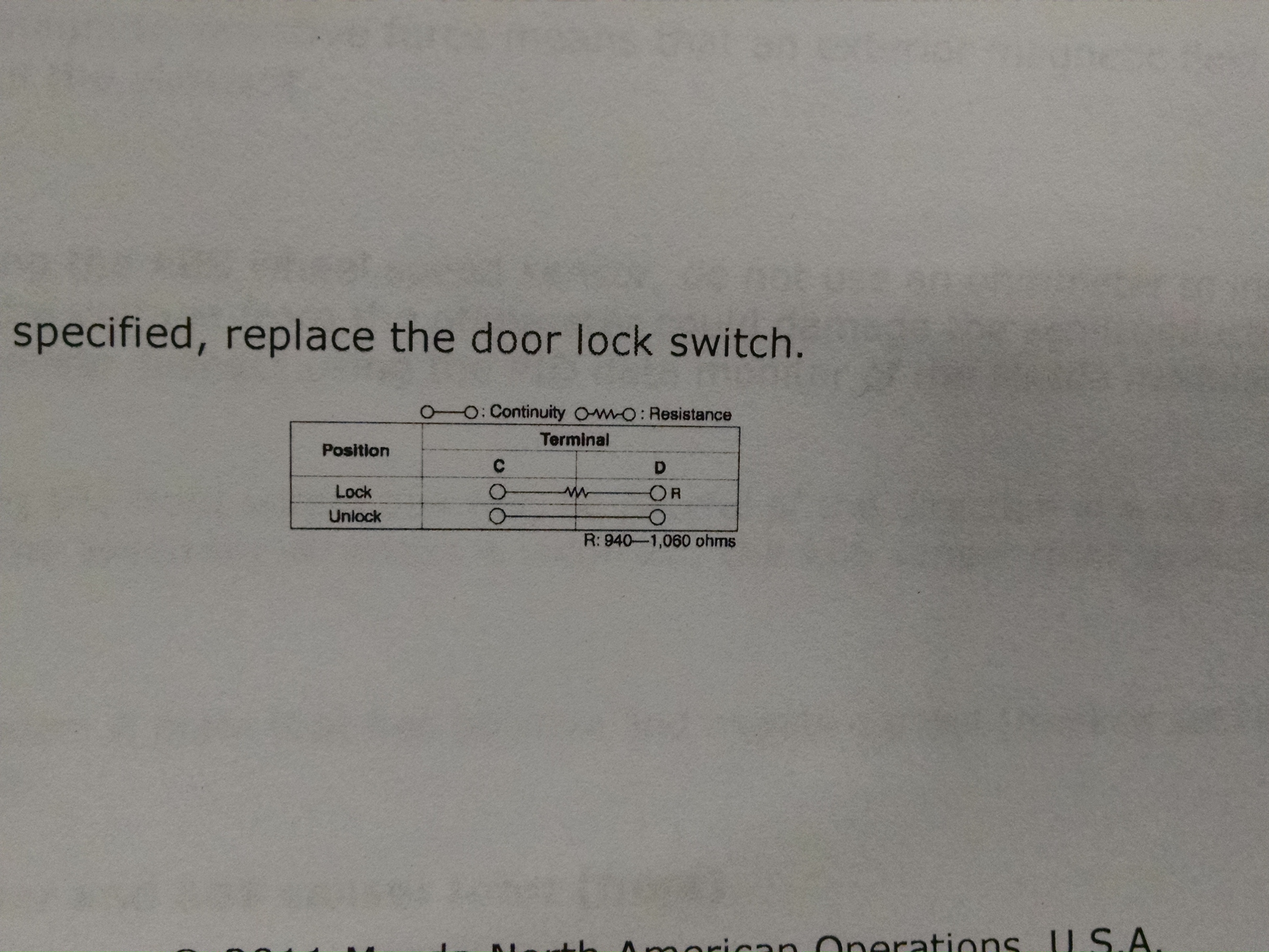
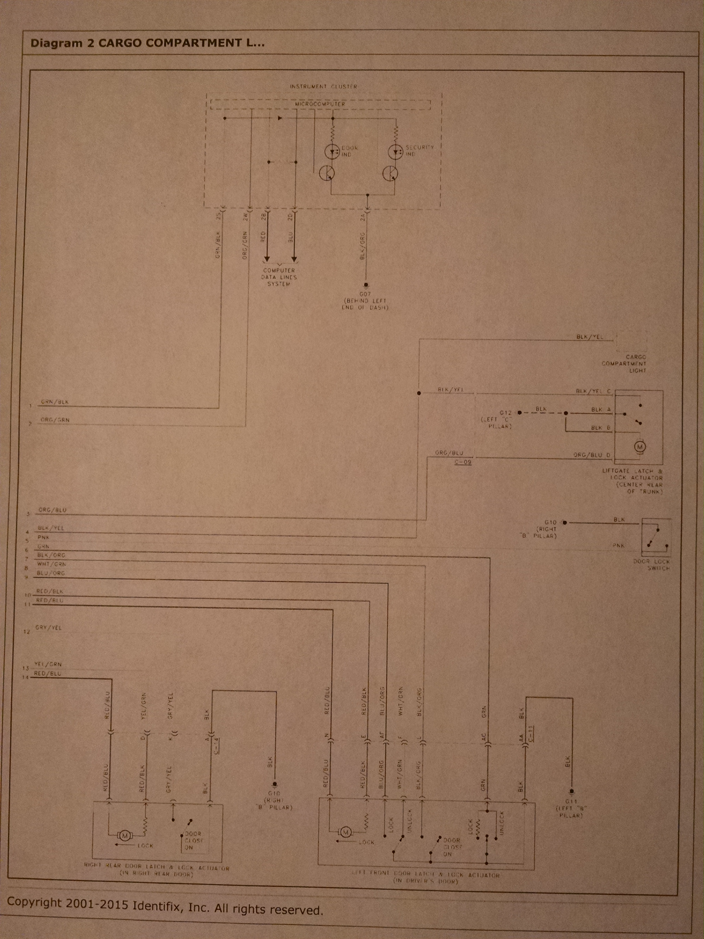
So it looks like the WSS signals would be a pain in the ass to tap into and make work, and the lock switch works like I expected. You need normal power to unlock, and 1000ohm resistor inline to simulate a "lock" command.
So it looks like the WSS signals would be a pain in the ass to tap into and make work, and the lock switch works like I expected. You need normal power to unlock, and 1000ohm resistor inline to simulate a "lock" command.
flatlander937
Member
- :
- '11 Mazda2 Sport
Why would we have to tap into the ABS? Is it that everything else would be shorted?
The cluster gets speed signal from the ABS module via the CAN bus, which gets signal from the ABS sensors.
If it must be speed related it will be tough being able to make it work without upsetting other modules or frying something.
This is why I recommended using RPMs from a coil to go into a frequency to voltage converter, and once it reaches X voltage it sends the lock signal. Then you need a way to disable it from doing it more than once per ignition cycle or it will lock every time you pass the set RPM.
flatlander937
Member
- :
- '11 Mazda2 Sport
Is it alternating current driving the speedometer? How much voltage is it? How shielded are those wires? Would a non-contact voltage tester be able to determine a baseline reading from it without tapping into the system?
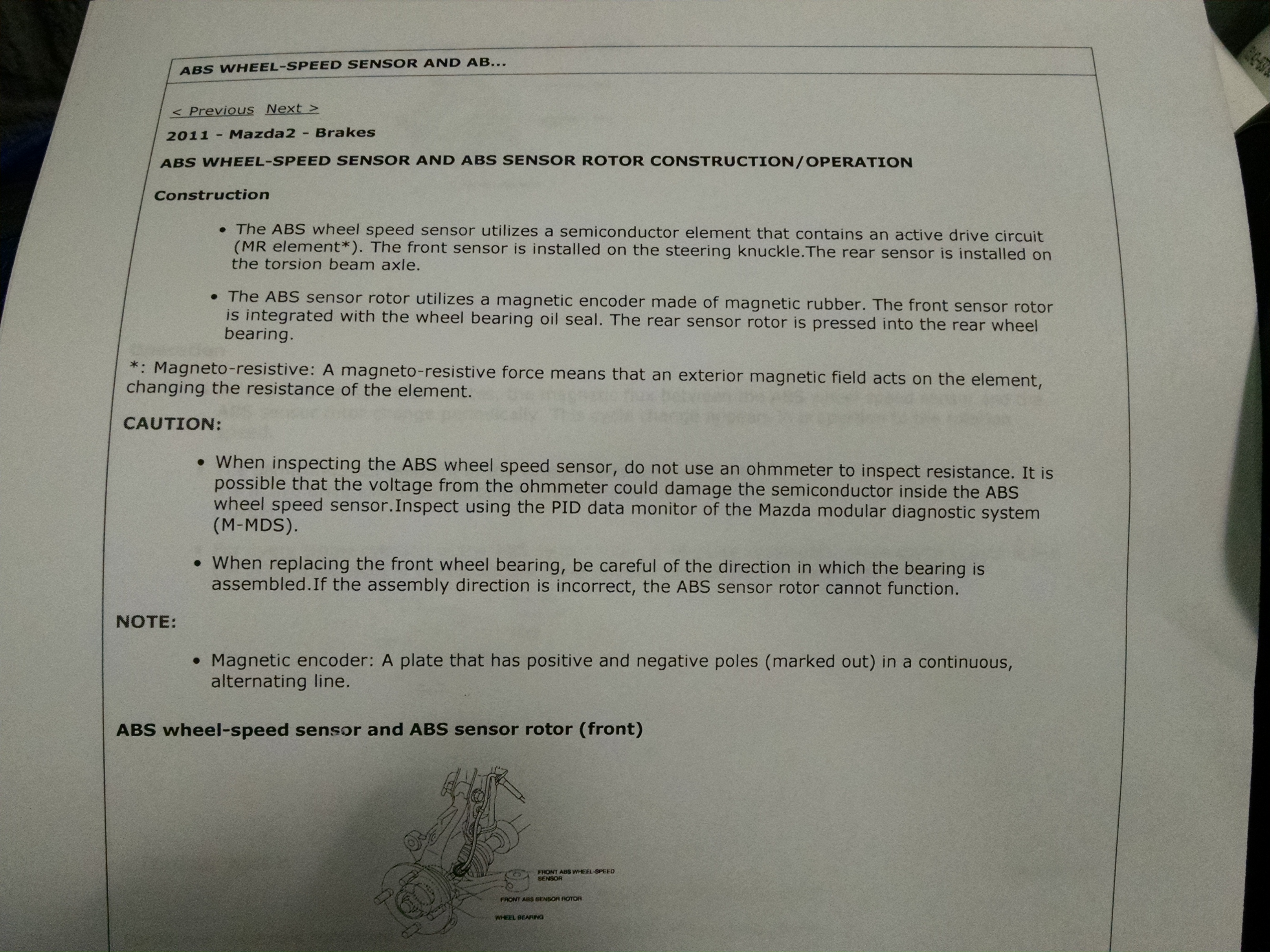
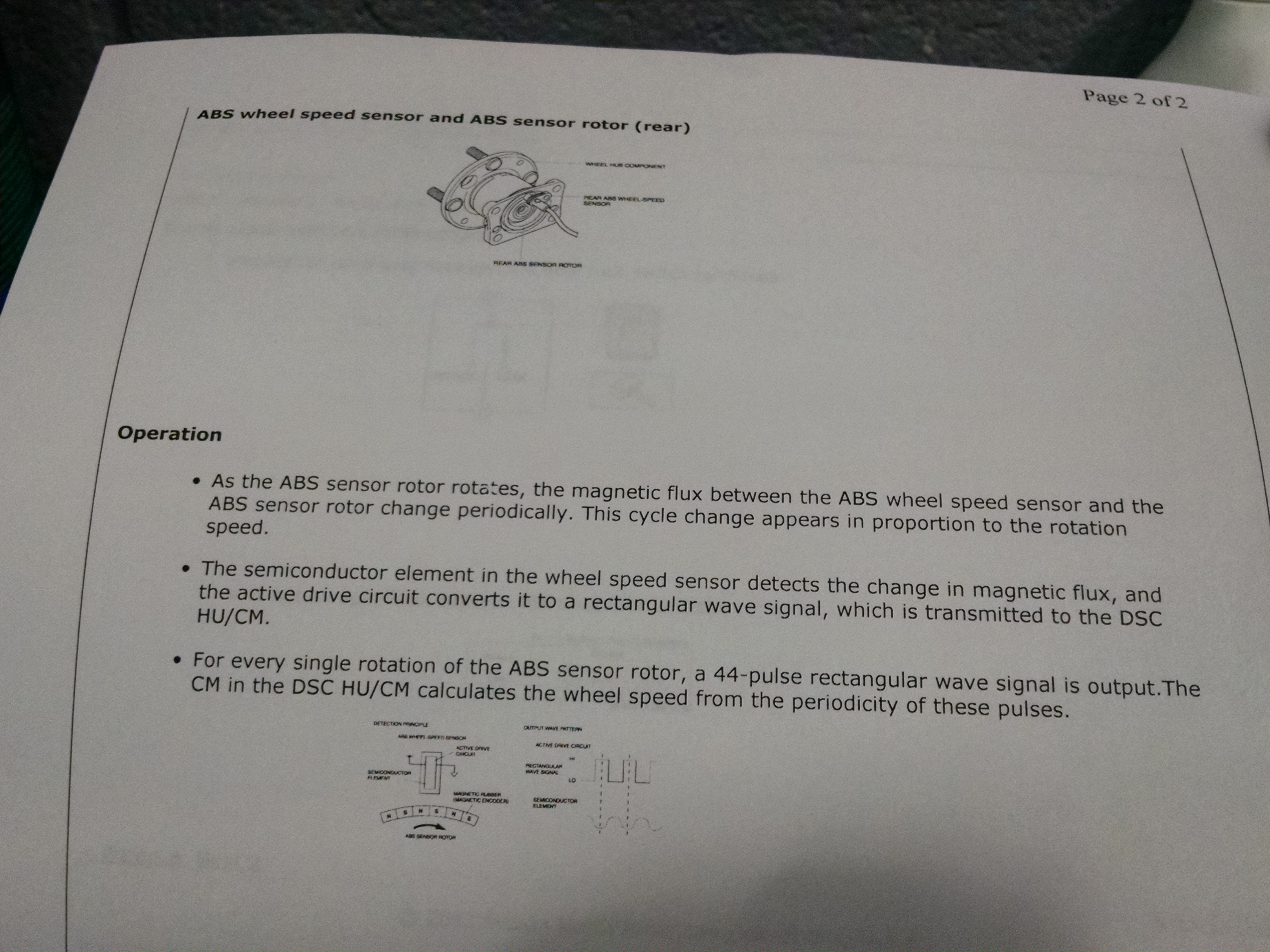
No. The signal from the wheel speed sensors I don't think is a true AC signal. As each tone wheel passes it changes resistance, it doesn't specify that it actually generates voltage like an AC signal would.
Mazdas descriptions are pretty broad.
This raw signal goes to the ABS module. The ABS module sends WSS signals to other modules over the CAN bus system. You need a CAN sniffer to decipher what is going on, even then its a lot of time to figure it out. Read up on CAN systems here:
https://en.m.wikipedia.org/wiki/CAN_bus
They're super complex in modern cars.
Not sure about your last question, haven't tried one on a WSS.
It's just resistance you can't check for(since it spikes a voltage through the sensor to do it... This is why you can't ohm out airbags without special equipment). You would want to backprobe it with an oscilloscope to see what it's putting out.
flatlander937
Member
- :
- '11 Mazda2 Sport
What type of CAN does the 2 use?
Are all of the wires twisted pair, or are there any interfaces?
It's Mazda's own CAN protocol probably for most stuff aside from the stuff regulated to one of the ISO standards.
I don't think you get how complex a full CANBUS really is. There are two wires that go to 4-6 modules or something like that in our 2, those two wires tell each module literally tens of thousands of things per second via varying voltage pulses at different rates many times a second. If you try and introduce a signal into it at the same time as a module is transmitting, you will 90% likely fry something. Best case scenario set codes.
Also, who makes the lock switch, and what's the part number for it?
Mazda. You can look it up here:
http://www.jimellismazdaparts.com
If you want to talk about the CAN bus complexities over a beer some time let me know, its not a simple subject and I'll admit I don't understand the really fine details of it fully on Mazdas, their info is pretty tightly guarded.
To get an idea of how sensitive these systems are, a while back when I worked at a Chrysler dealer we had a slew of Magnums/Chargers/300s that fried just about every module in the car when the radio was wired incorrectly.
Joe at Dynotronics may have some input or could share some stuff. I inquired about having launch control/2-step no-lift-shifting programmed in a while back, which would only require info in the ECM(one module, not ABS and ECM like your goal) and it would take so long to test it out and write the code and I may still not work, that it would be cost prohibitive to bother with for now.
Last edited:
I probably don't at the moment. I admit I've had only some background in signals processing due to some previous coursework in cryptography and communications networking, and my understanding of electronics is minor. I'm attempting to find as much literature as I can on the topic to get a better appreciation for it.
Similar threads
- Replies
- 0
- Views
- 351
- Replies
- 1
- Views
- 912