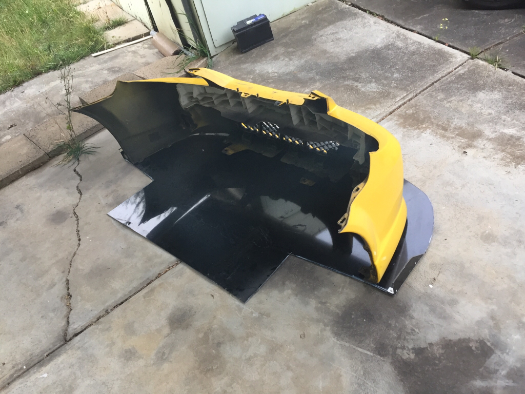
It's made from Alucobond which is a type of aluminium composite panel. Basically 2 thin layers of aluminium with fire retardant plastic sandwiched in between.
The beauty with our cars is that there are bolt holes everywhere! I removed the lower engine covers and removed the front bar and made a cardboard template which allowed me to get the mastic shape and cut out where the exhaust manifold and the sump sit as they are quite low in our cars. I also used some stainless steel brackets which are bolted through some existing front holes in the front panels.
Once I got the basic shape it was a matter of fitting and trimming till it sat just right. Fixing it to the radiator support and the cross member was pretty straight forward too. And I cut the original lower engine covers so the sides are still in place as they have bolts in the wheel well. I just zip tied them to the splitter so they don't flap about.
Once it was all set I painted it, tested it and reinforced it with "L" shaped aluminium brackets and high tensile bolts in places that were lacking in support (sides and very front).
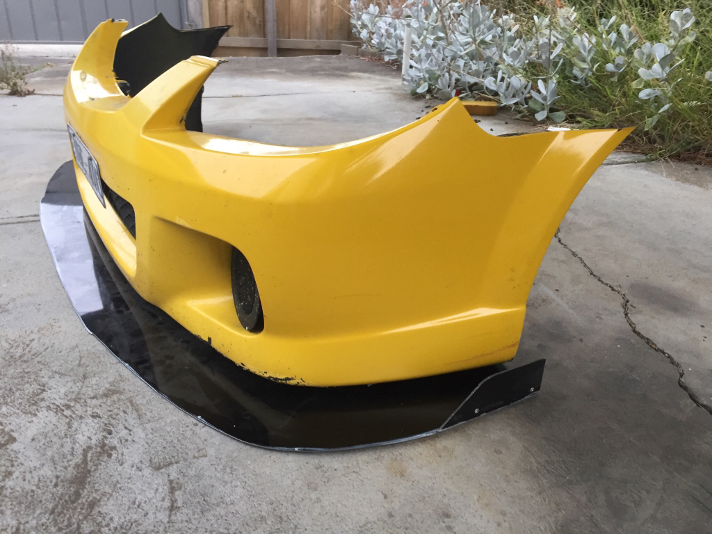
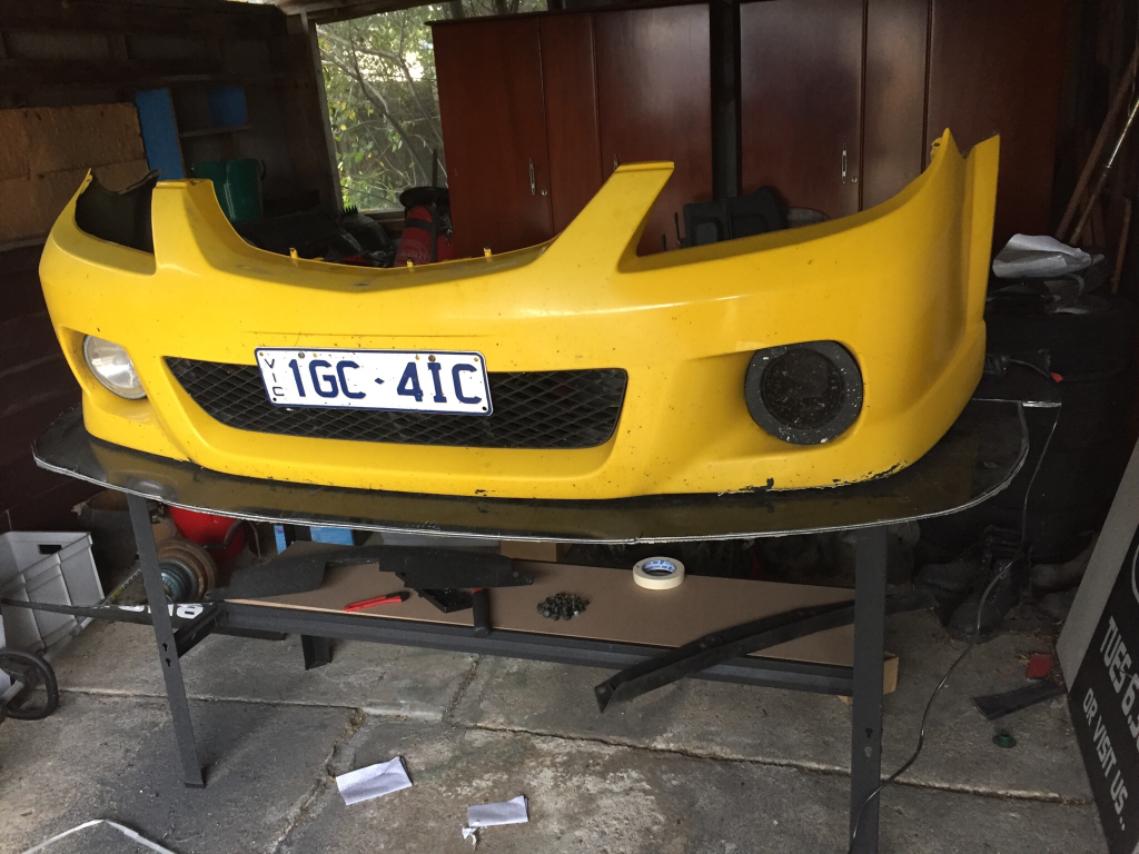
The thing with the protege5 is that the front bumper is on a positive angle from the front wheel arch to the front, so the hardest part was making it level. You can't attach it to the bumper like you see them do it on the YouTube channels when you search "DIY front splitter". The second hardest part is finding a suitable material long and wide enough to fill in the gap between the splitter and the bumper. If you can get long enough "L" shaped rubber then that works best as you can just screw it under the bumper and it moulds easily. But I can't find any from anywhere. Putting bends in a flat piece of rubber won't work, and I didn't want to use aluminium and rivet it to the front of the bumper. Another way would be to get a generic front lip off some other car which is squared, similar to ours. Like for an Impreza or an older civic, cut it to shape and fasten it, so it sits level.
My bumper is now only supported by the 2 top bolts, side bolts and the guard liner clips. There isn't any support underneath as access is restricted by the splitter and the splitter will absorb the impact from the bottom/ front rather than the bumper itself.
It was a fun project, it took a few days to make but I was really happy with the result. I did it all with an angle grinder to cut everything and then a sanding disc to fix up the edges.
Sent from my iPhone using Tapatalk