krimson_viper
Member
- :
- 2010 Mazda 3 I touring
I haven't done a write up in awhile, and I haven't done car audio in about a decade, and never one of this level. I'm an amateur at best, so bare with me while I go through this thing. I originally posted this in another forum, but this place isn't riddled with glitches that send my phone to an app download, mobile looks better, and there's more traffic so my questions can be answered. Please let me know if the pics are a decent size. If they're too big I will resize them, but I usually don't notice.
My car is a 2010 Mazda 3i-Touring with Bose and Moonroof(I believe it was called the tech package?) and manual. In this build I'll be keeping the head unit. My stock system became plagued with an amp problem that seems to be occuring in a good amount of Bose systems apparently. I've been without a sound system for about 2 years now and it's about time I corrected that!
I haven't seen a sedan have this of an extensive audio system put in and there have been some differences from the Speed3 and the sedans. This thread will address those differences and how I worked through them. I've already started installing somethings because I'm impatient, but I'll post pics as I tackle new areas and revisit areas. I'll try my best to document everything so that following nooberts can learn.
Speaking of being a noob, these are the two threads I have referenced for myself:
http://mazda3revolution.com/forums/...-electronics/70569-my-full-audio-install.html
ETERNAL's 2010 MS3 SYSTEM BUILD LOG***UPDATE 13 DECEMBER PAGE 6...COMPLETED*** - Mazda3 Forums : The #1 Mazda 3 Forum
Thank you so much to Eternal and pdc001 for your hard work! This wouldn't have been accomplishable if it weren't for your expertise and the hardwork you both put into your builds. Thank you.
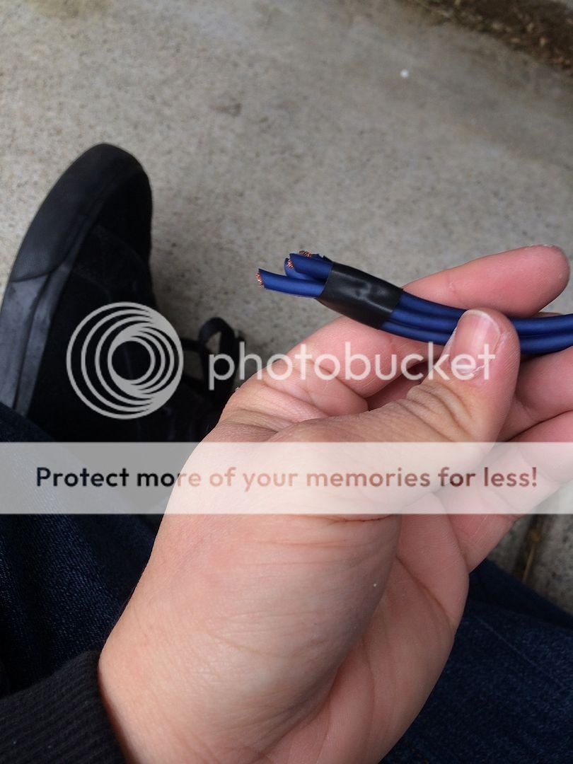
For the most part, I stuck with Stinger equipment. I did a bit of research and they seem to have one of the best conducting wires and insulation for the price. Most brands seem to have aluminum in their wires which hinders power transferring, while Stinger is 100% oxygen free copper(OFC). From there, I just stuck with Stinger everything for OCD reasons. I went with 4AWG wiring because I'm under 1000 watts RMS. The typical consensus I've read is 8AWG for 0-500 watts, 500-1000 is 4AWG, and higher than that is 0AWG.
What I've ordered so far, all from Amazon:
PAC LOC - PAC AOEM-MAZ2
4000 Series amp kit
MIDI fuse holder
3 Pack MIDI 100 amp fuses
1/0AWG distribution block (has the 4AWG reducer in package)
50' KnuKoncept 16AWG (I know, I bought this before I researched. I might need more footage anyway.)
5' 10AWG wire
2 4AWG AGU fuse holder
1 Pair of 4AWG ring terminal
1 Pack of 40 AGU fuse
1 Pack of 50 AGU fuse
2 Y-Adapter RCA cables
1 Generic 12'' speaker box (To be ordered)
**Waiting to see how much cable I can salvage from the amp kit before I order more wire. I'll need it for the second amp to the distribution block and second amp power and grounding. I can wait on this for right now though because my sub amp and sub haven't been ordered yet.
My equipment (I'm a JL fanboy, ha):
JL Audio XR570-CSi
JL Audio C2570-CXi or C2650CXi (Not ordered yet, not sure of the size required)
JL Audio 12W6v3 (To be ordered)
JL Audio 300/4v3
JL Audio 600/1v3(To be ordered)
Monster Cable RCAs for 4 Channel
Tsunami RCA for mono
Head unit removal and LOC install
Tools:
1 Philips screwdriver
2 pairs of sturdy hands with sturdy fingers
Zipties
Wire hanger(to run the wire to tight places)
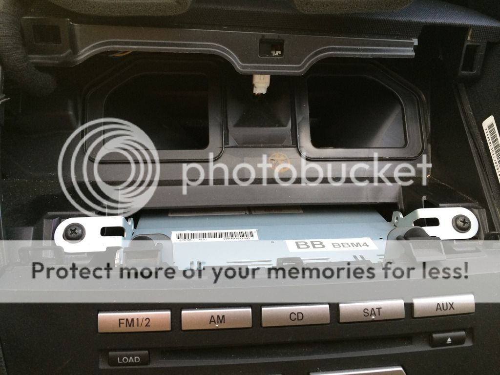
At the top of the headunit are two vents that literally slide forward with enough coercion from your fingers.

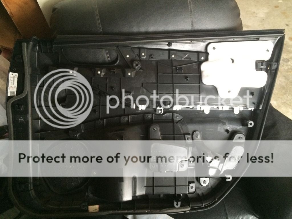
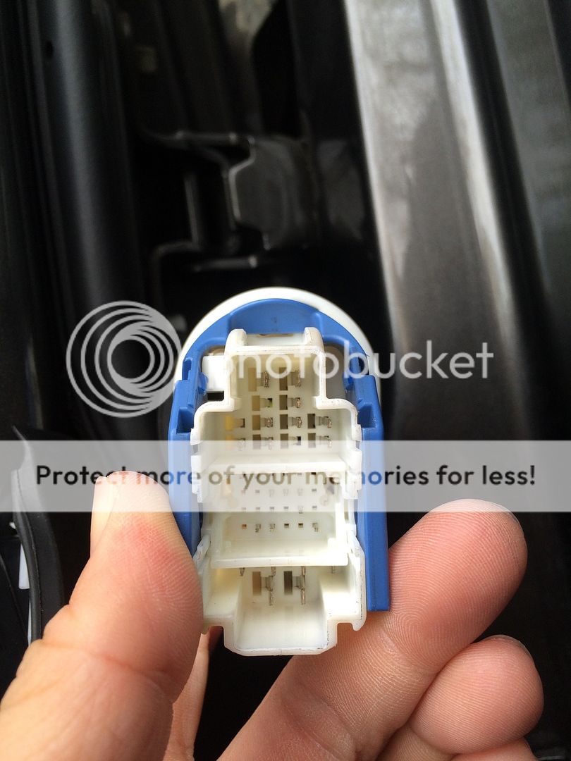
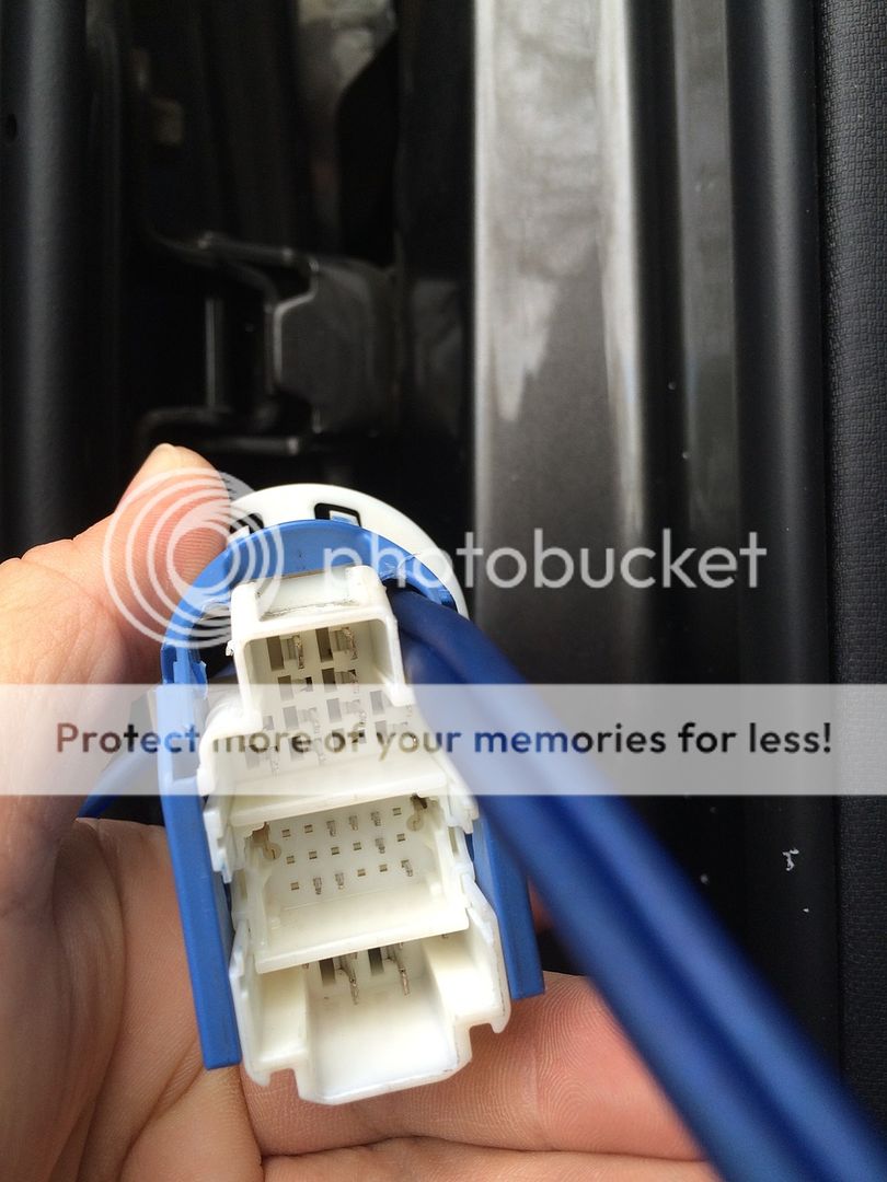
When you have that detached, you can just flip it on it's head for the remainder of this step. There will be two big screws that will be attached the the head unit's tabs Remove the screws, and the radio itself will slide forward as well. Be warned, if you pull too hard, you might damage your temp control area with scratches because the wires plugged into the head unit are a little short. They are in the head unit through simple plugs that you pinch off to remove.
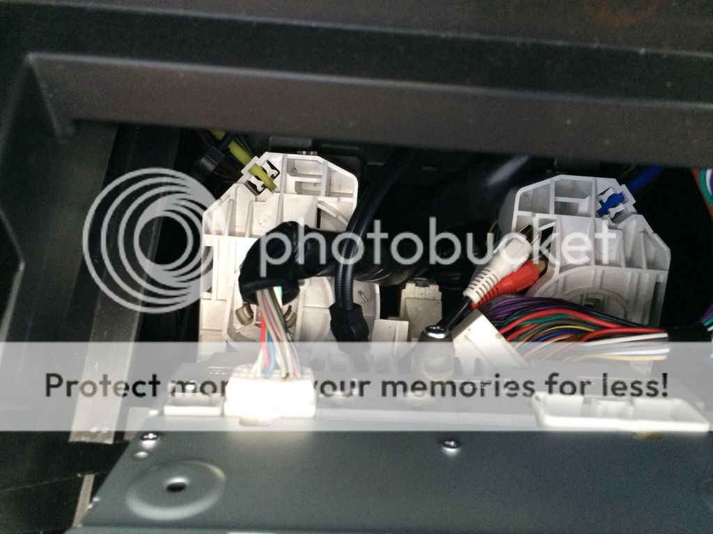
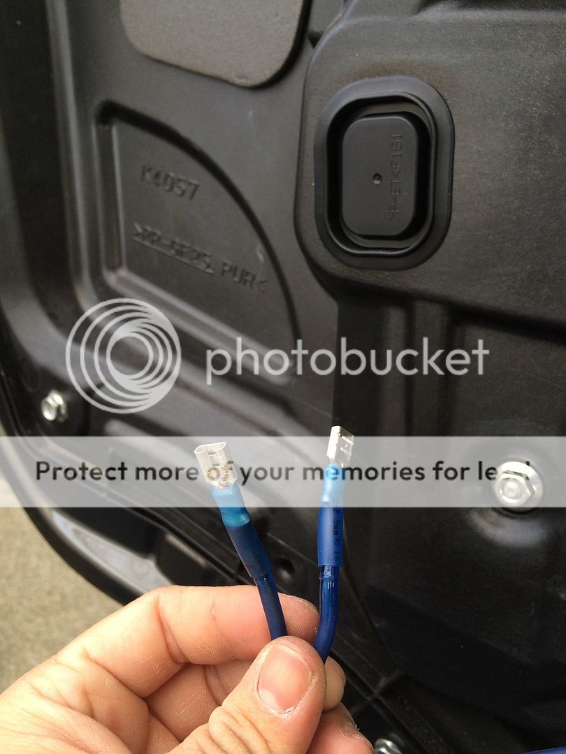
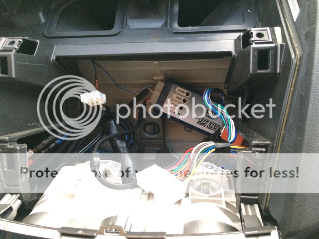
I've already installed the LOC and it was simple plug and play. No splicing of wires required at all, just a simple crimp of the remote wire through a butt connector and additional heat for the butt connectors heat shrink.
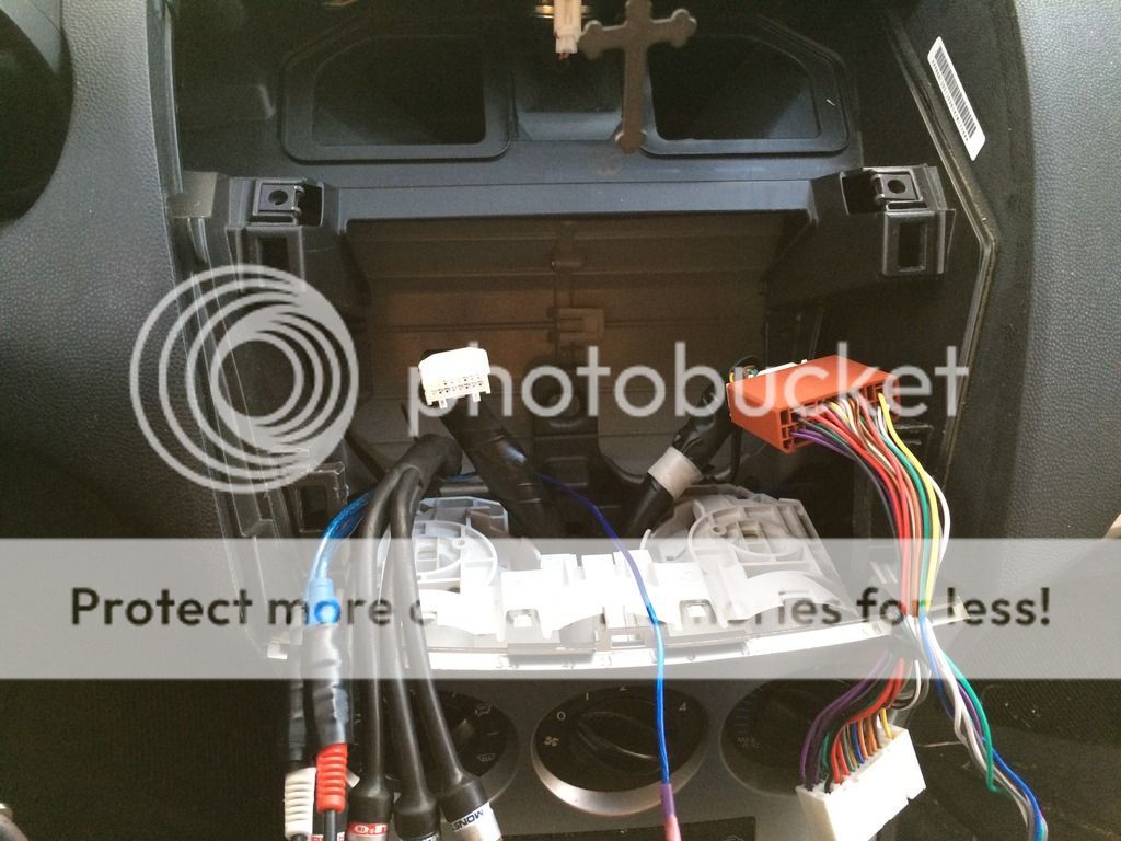
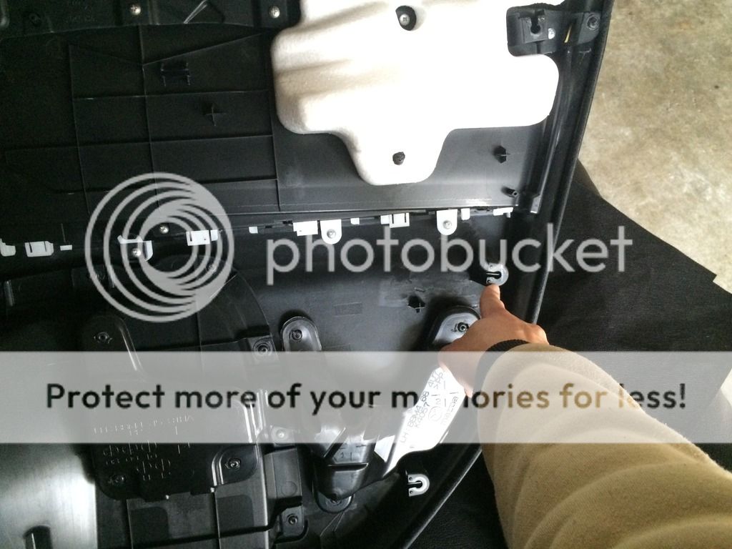
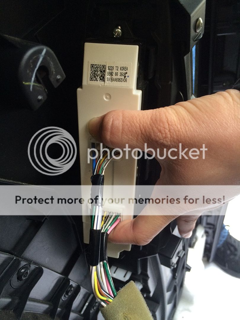
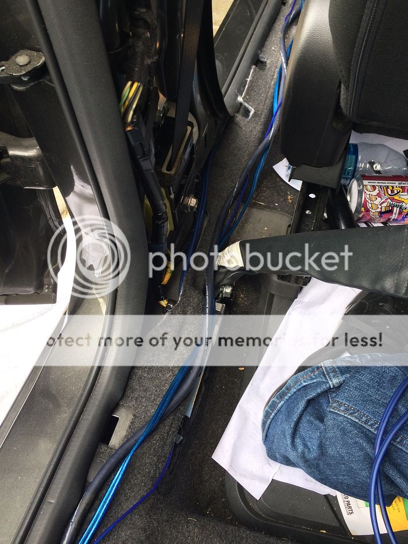
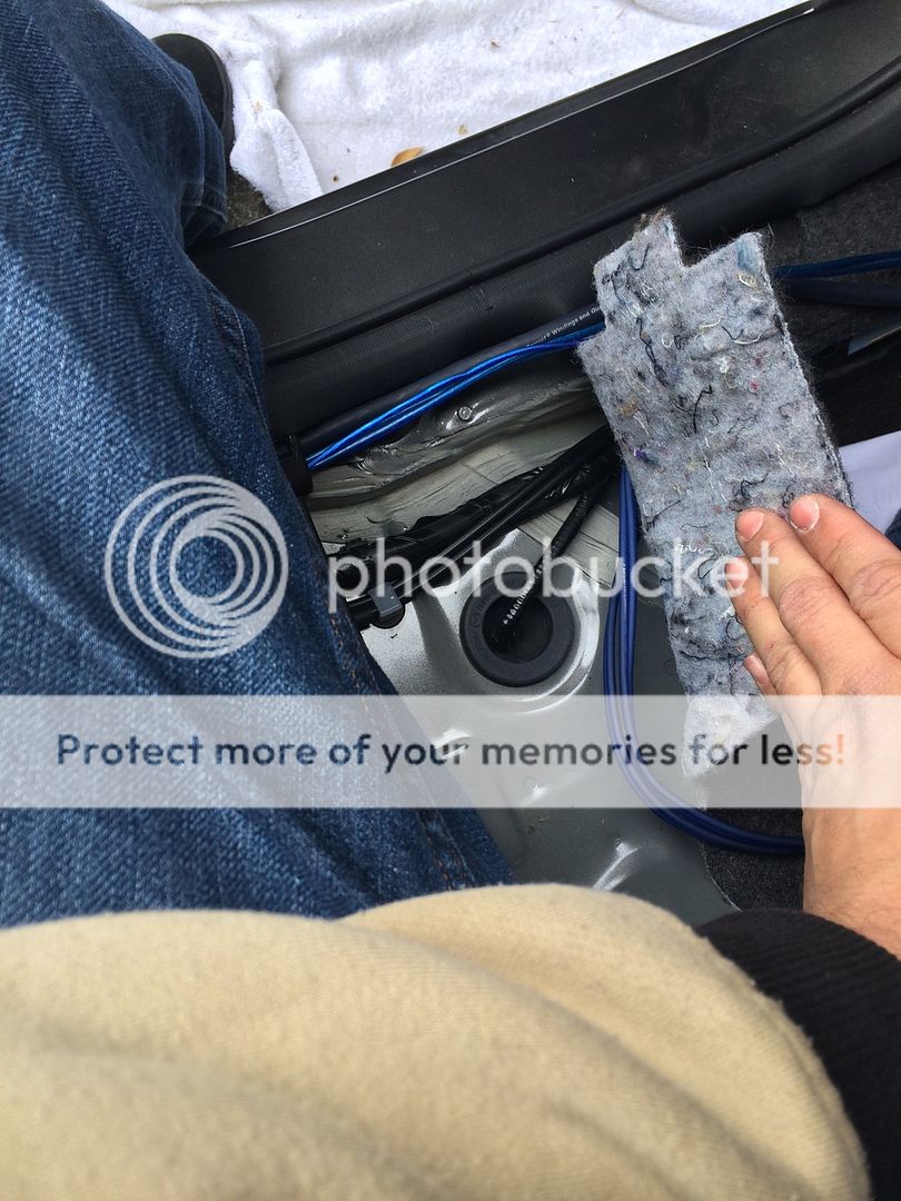
I came across my first noticeable difference between the Speed3 and my car. I have no space under the headunit for the LOC. Instead, I had to move the cables to the left of the unit(possibly to the right as well). the LOC sits directly behind the head unit
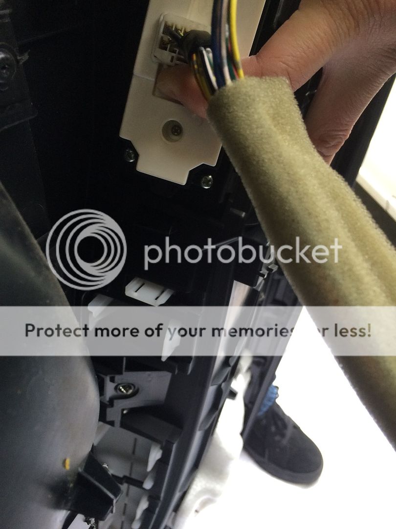
I ran the cables and remote through a hole I found and zip tied it into place.
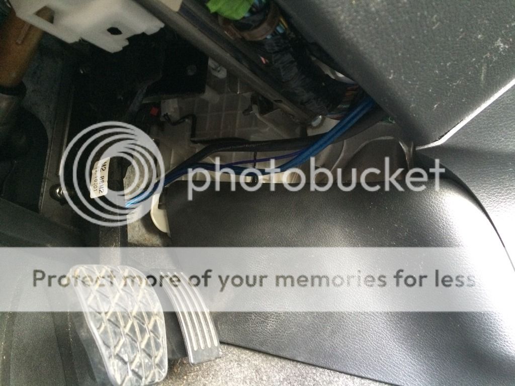
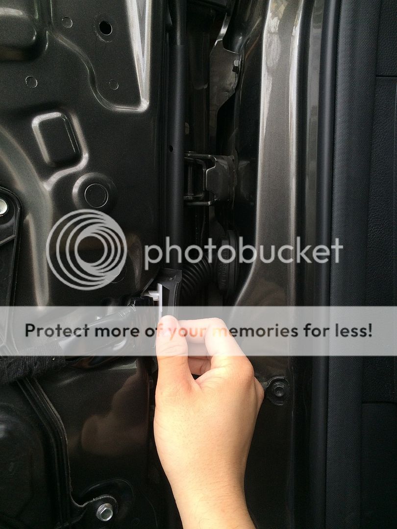
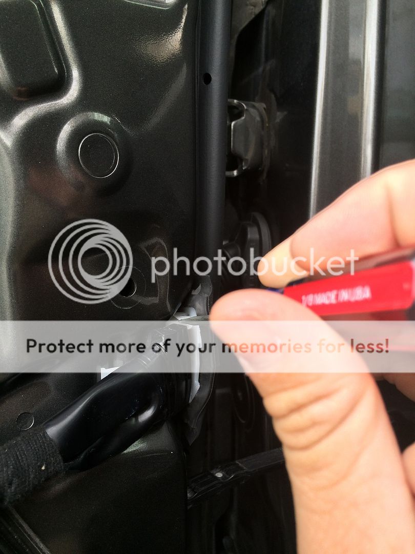
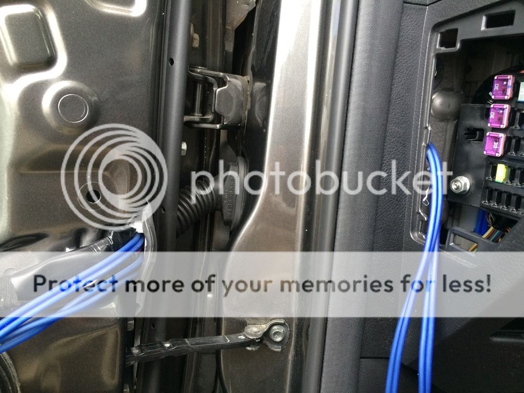
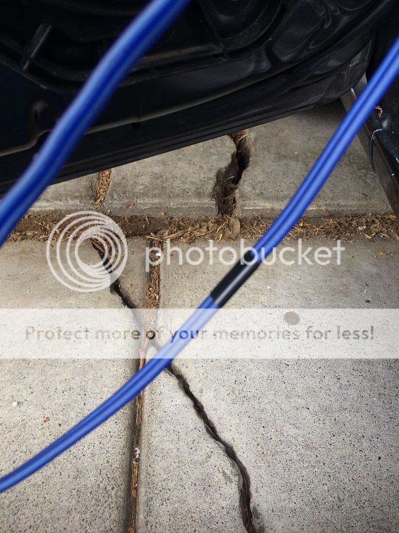
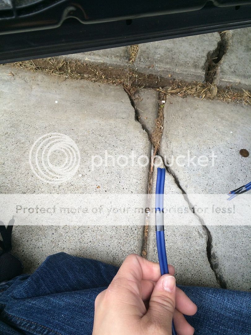
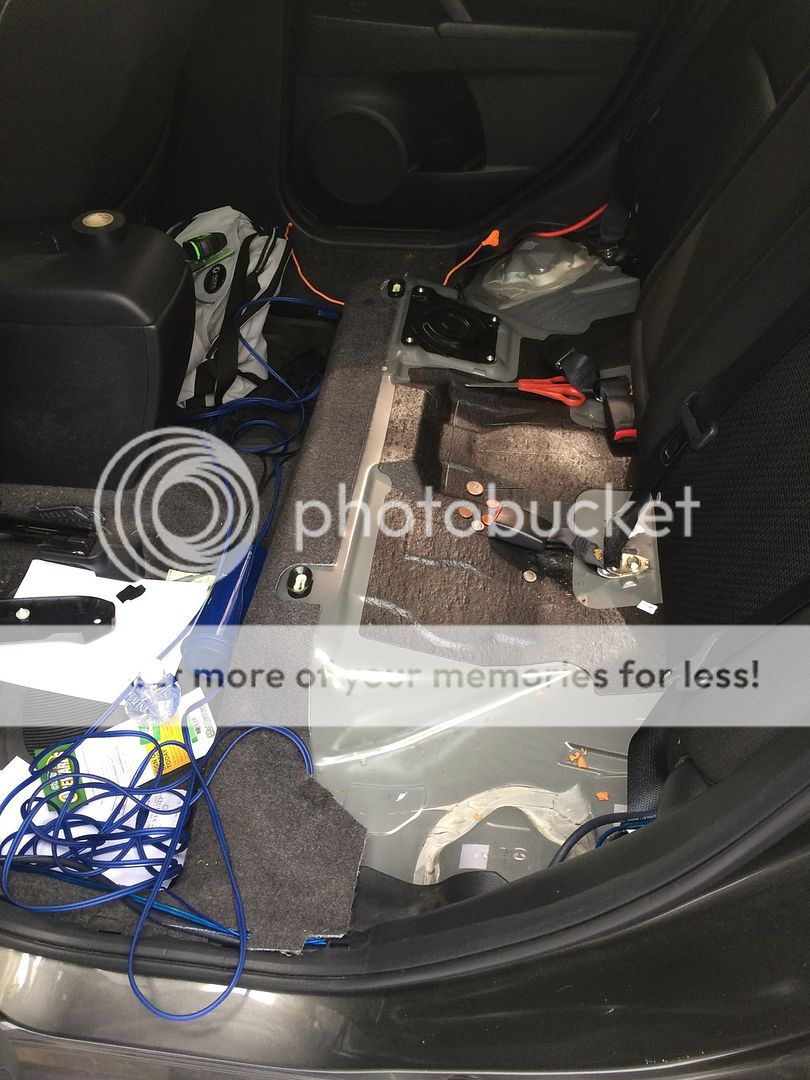
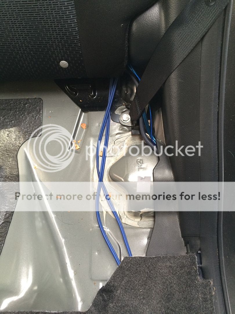
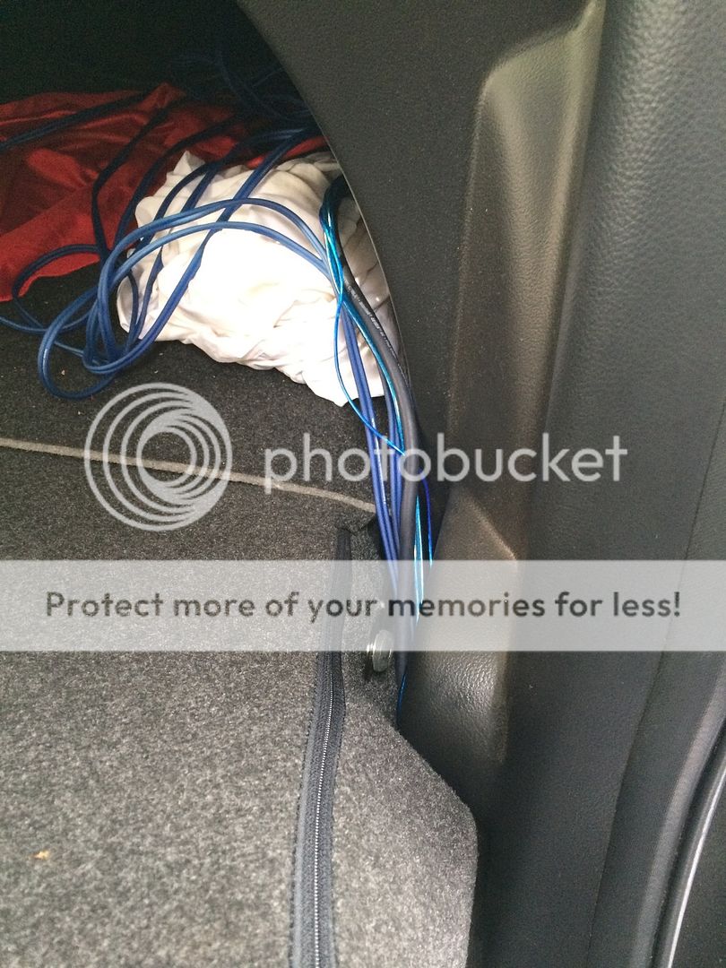
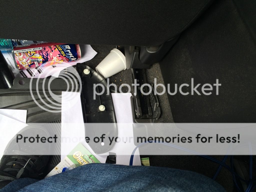
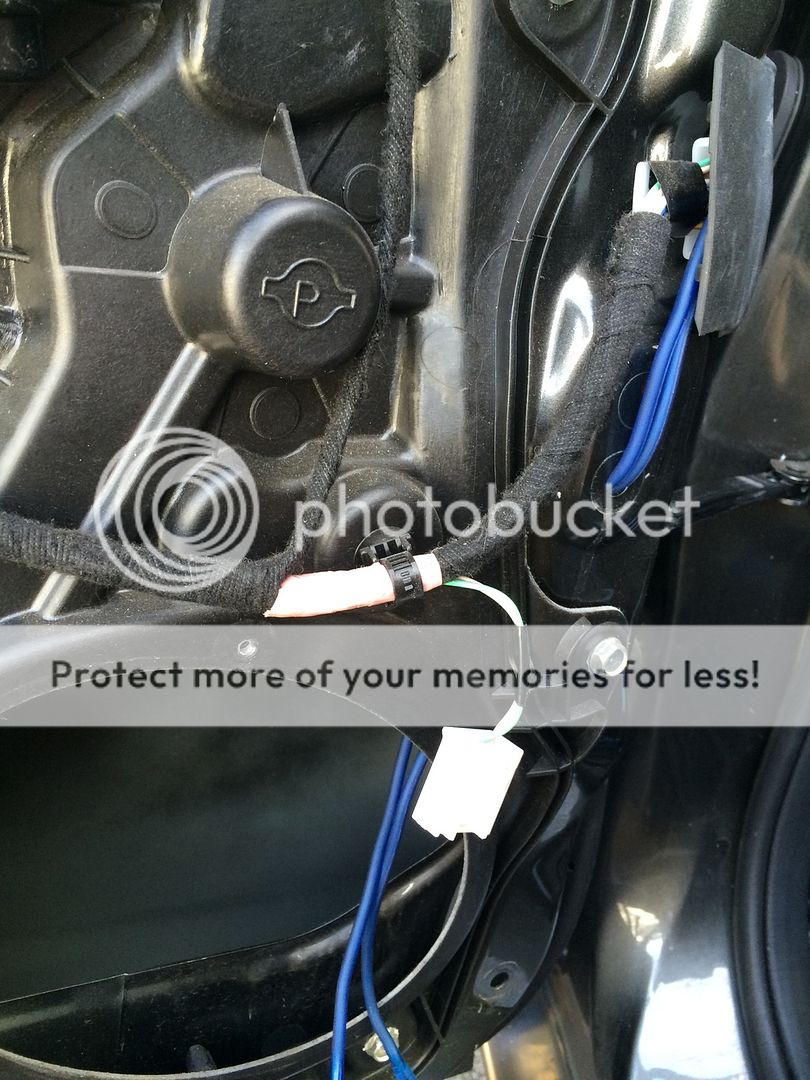
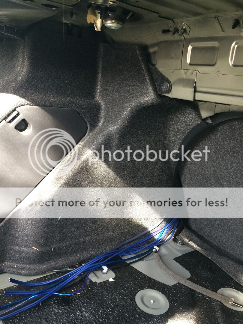
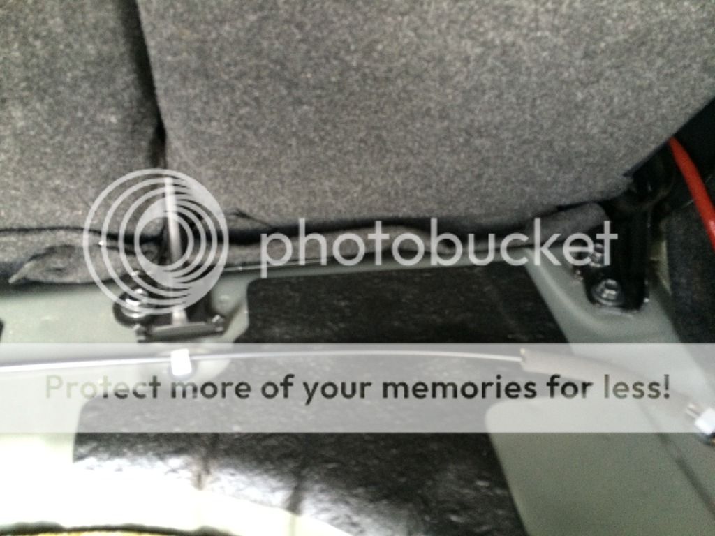
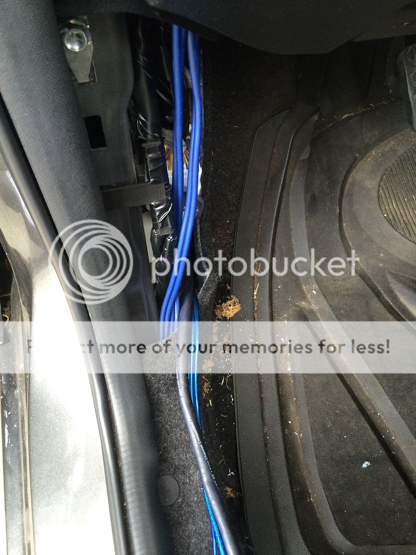
I then ran them under the carpet to the kick panel and under the door sill to the back. To do this, I needed to remove the kick panel and door sill. The kick panel has a simple pin holding it in place. Pull the center dot out and the whole thing will follow. This picture is after I ran the new speaker wire from the door.
Remove the door sill by gently and firmly pulling it up. Next, move the kick panel. Becareful. You'll need to wrestle the rubber off of a hook attached to the kick panel and pull the kick panel along the door sills trajectory. I broke my driver's side kick panel.
Power wire install
Tools:
Philips screw driver
Power drill
7/16 drill bit
*another drill bit will be needed and listed when I find one for another job
12mm socket
10mm socket
Ratchet
Proper fitting rubber grommet (I just randomly found one that fit)
Pam spray (for lube on wire through grommet)
Zipties
Remove the neg battery terminal and secure it in a way that it won't bounce back to original position. I'm not going to pic this because if you don't know how to do this, you shouldn't be installing your own system.
The battery box has a slight opening on the left of it that will allow your cable to slide though with out having to hack the battery box. You will need to attach the O-ring terminal like this in order to do this.
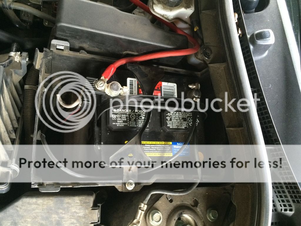
I left the fuse out of my fuse box so that I don't have to worry it being a live wire while the power wire is sitting for actual usage.
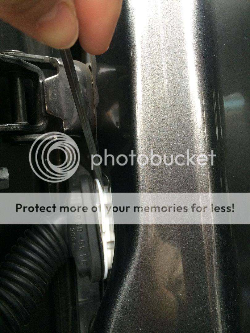
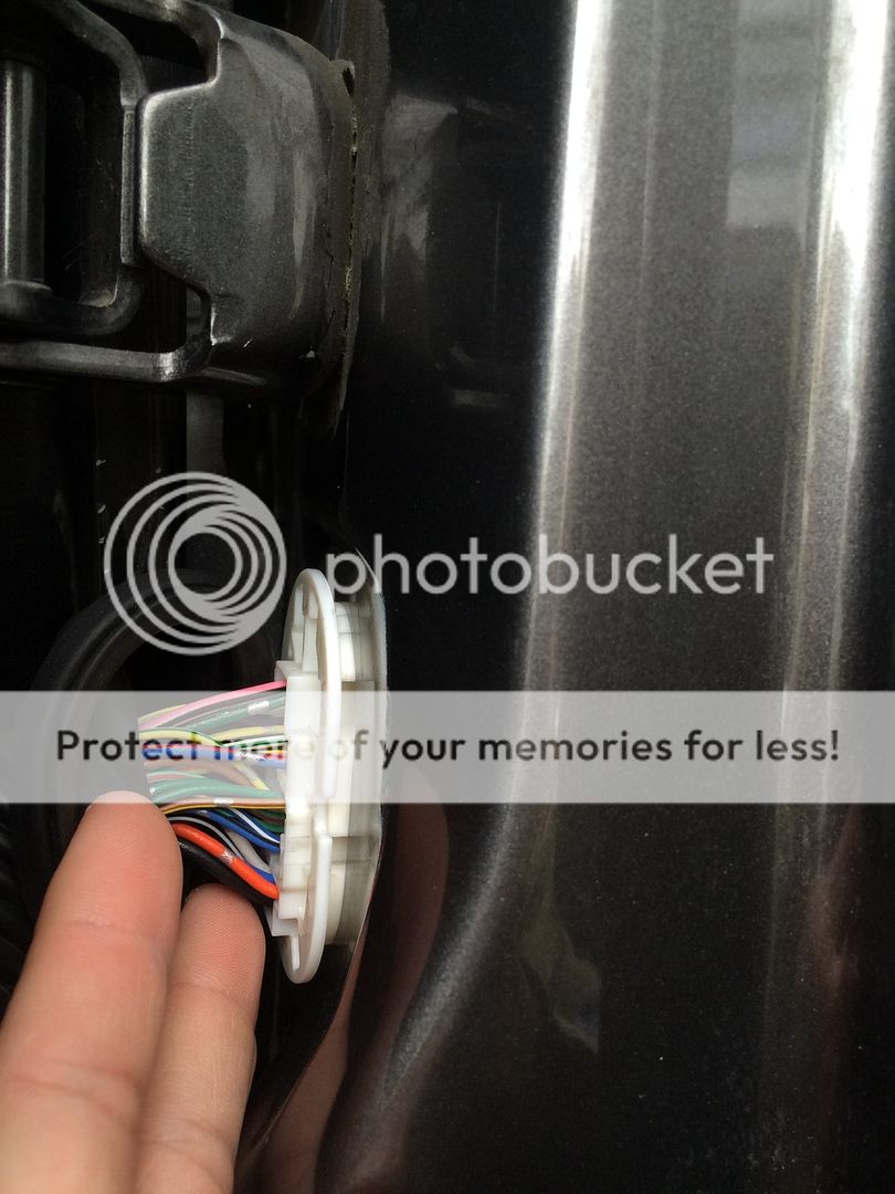
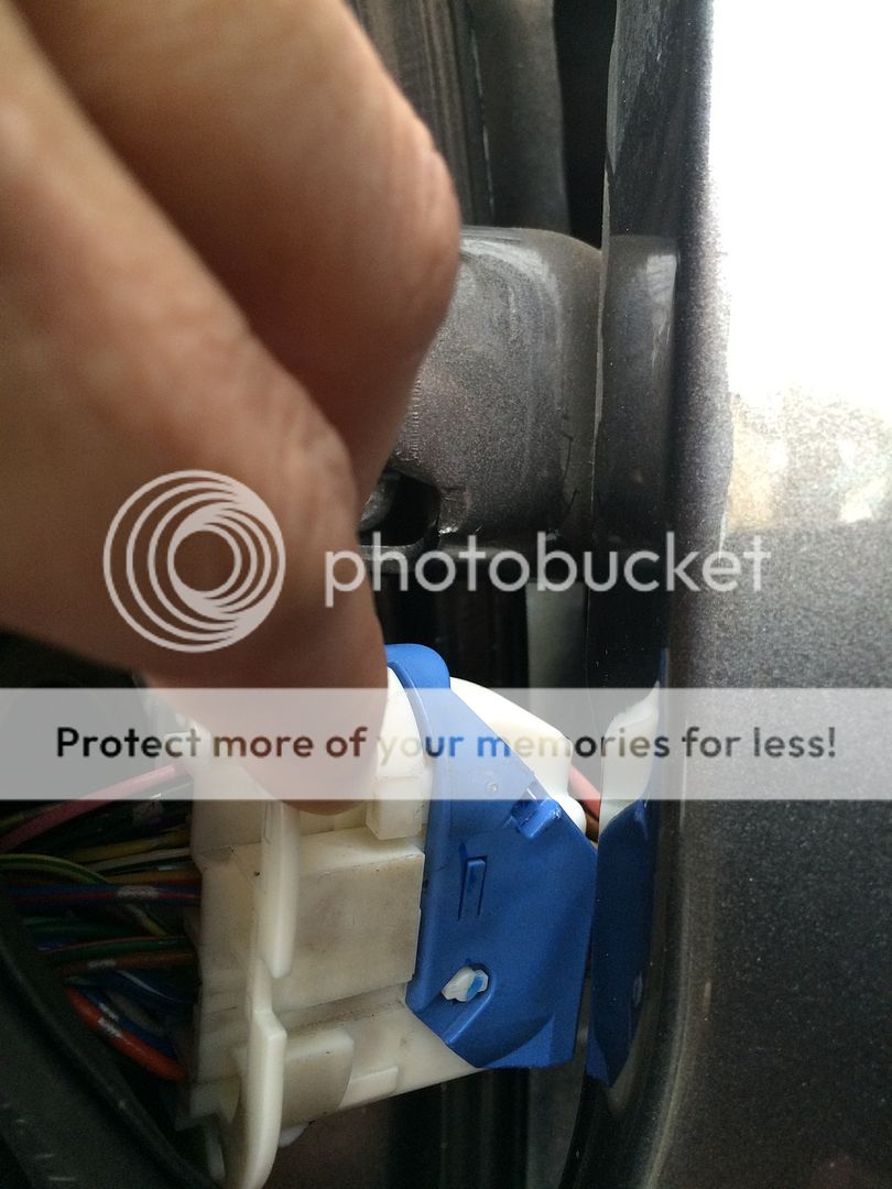
Next you will need to drill through the firewall. The place you'll need to drill through is where the Speed3's have that rubber/plastic disc.
For the sedan, it's a solid firewall with no where to run a stray wire. I have heard of people who own an automatic 3 and can run an 8AWG through a rubber boot that runs along the steering column or the place where the clutch goes. Unfortunately this isn't possible for us, but it's better we go through the firewall anyway. The power wire for the original Bose system is on the right side anyway and you want to always run the RCAs where large power wire aren't. Whine can seep into the audio system that you can't eiminate if these 2 wires are next to each other.
To get to this desired spot you will need to remove the glove box. The glove box door is held in place by clips. If you run your hands along the door downwards, you'll find a nice grip and firmly pull. IIRC, there are 4 clips and a 5th one will need to be unhooked on the right. You will see this lonely 5th hook without even attempting this removal.
(Will insert pic later)
Next, there are 2 screws holding the glove box securely.
(Will insert pic later)
(Will insert pic later)
Before continuing, remove the kick panel and door sill. Now you will pull the glove box towards the seat. You should notice the rubber seal on the right that runs all along the door opening.
(Will insert pic later)
There will be a wires that's attached to some lighting inside the glovebox and to the bottom of the glove box for some kind of ambient lighting system. The ambient lighting at the bottom has 2 clips you can unattach easily. The glovebox light will need to be unscrewed.
Here's the preferred area for you to drill.
(Will insert pic later)
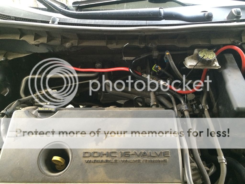
Voila! Entry into the engine bay from your cabin. Put a rubber grommet that's nice and snug for your wire and small enough for your hole. You will use Pam cooking grease that's lightly applied to your fingers to get the wire through the grommet. Feed the wire from your engine bay. Mark an area on the wire with eletrical tape to determine a stopping point. You will need just enough to attach to your fuse box.
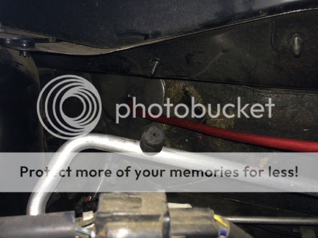
I will find a better place for my power wire and fuse box. I'm not happy with how much wire is just in mid air, even though it's secured extremely tightly in place. This is where I will use the undetermine drill bit mentioned earlier. I will drill holes somewhere along the edge to zip tie the wire and fuse box. Amp kits predetermine the distance for the fuse box and can limit where you place the fuse box. The fuse box should always be close to the battery. IIRC, 18 inches is the max distance from the battery.
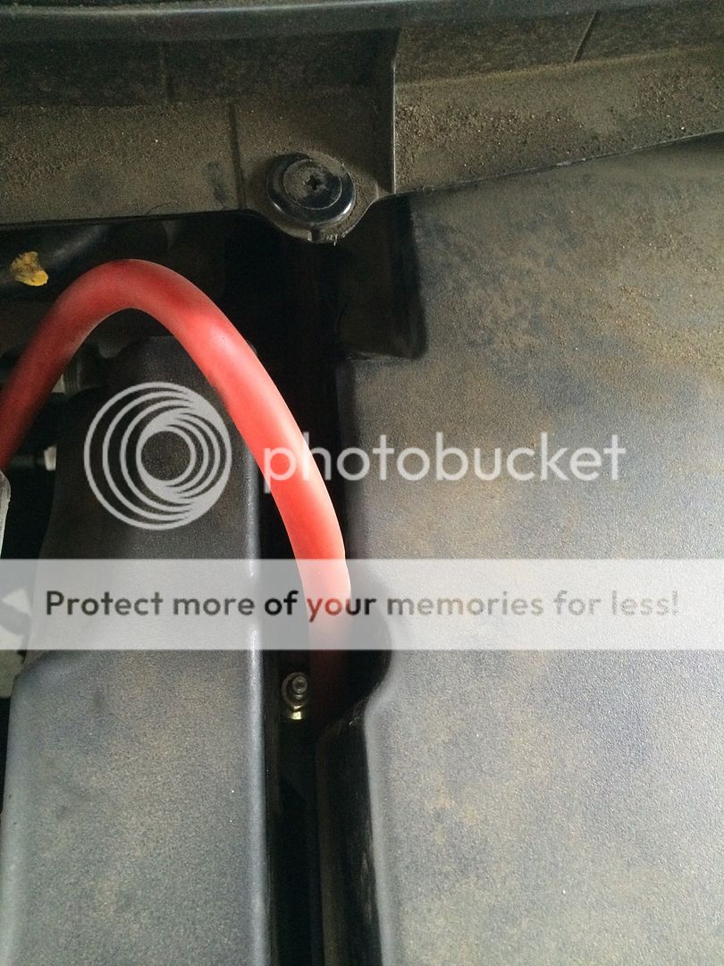
This is how I reran my wire. I removed two plastic screws that hold something and I just ran zipties to hold my wire down and whatever those screws were holding.

Now run the power wire the same way you ran your RCAs on the opposite side.
My car is a 2010 Mazda 3i-Touring with Bose and Moonroof(I believe it was called the tech package?) and manual. In this build I'll be keeping the head unit. My stock system became plagued with an amp problem that seems to be occuring in a good amount of Bose systems apparently. I've been without a sound system for about 2 years now and it's about time I corrected that!
I haven't seen a sedan have this of an extensive audio system put in and there have been some differences from the Speed3 and the sedans. This thread will address those differences and how I worked through them. I've already started installing somethings because I'm impatient, but I'll post pics as I tackle new areas and revisit areas. I'll try my best to document everything so that following nooberts can learn.
Speaking of being a noob, these are the two threads I have referenced for myself:
http://mazda3revolution.com/forums/...-electronics/70569-my-full-audio-install.html
ETERNAL's 2010 MS3 SYSTEM BUILD LOG***UPDATE 13 DECEMBER PAGE 6...COMPLETED*** - Mazda3 Forums : The #1 Mazda 3 Forum
Thank you so much to Eternal and pdc001 for your hard work! This wouldn't have been accomplishable if it weren't for your expertise and the hardwork you both put into your builds. Thank you.
For the most part, I stuck with Stinger equipment. I did a bit of research and they seem to have one of the best conducting wires and insulation for the price. Most brands seem to have aluminum in their wires which hinders power transferring, while Stinger is 100% oxygen free copper(OFC). From there, I just stuck with Stinger everything for OCD reasons. I went with 4AWG wiring because I'm under 1000 watts RMS. The typical consensus I've read is 8AWG for 0-500 watts, 500-1000 is 4AWG, and higher than that is 0AWG.
What I've ordered so far, all from Amazon:
PAC LOC - PAC AOEM-MAZ2
4000 Series amp kit
MIDI fuse holder
3 Pack MIDI 100 amp fuses
1/0AWG distribution block (has the 4AWG reducer in package)
50' KnuKoncept 16AWG (I know, I bought this before I researched. I might need more footage anyway.)
5' 10AWG wire
2 4AWG AGU fuse holder
1 Pair of 4AWG ring terminal
1 Pack of 40 AGU fuse
1 Pack of 50 AGU fuse
2 Y-Adapter RCA cables
1 Generic 12'' speaker box (To be ordered)
**Waiting to see how much cable I can salvage from the amp kit before I order more wire. I'll need it for the second amp to the distribution block and second amp power and grounding. I can wait on this for right now though because my sub amp and sub haven't been ordered yet.
My equipment (I'm a JL fanboy, ha):
JL Audio XR570-CSi
JL Audio C2570-CXi or C2650CXi (Not ordered yet, not sure of the size required)
JL Audio 12W6v3 (To be ordered)
JL Audio 300/4v3
JL Audio 600/1v3(To be ordered)
Monster Cable RCAs for 4 Channel
Tsunami RCA for mono
Head unit removal and LOC install
Tools:
1 Philips screwdriver
2 pairs of sturdy hands with sturdy fingers
Zipties
Wire hanger(to run the wire to tight places)
At the top of the headunit are two vents that literally slide forward with enough coercion from your fingers.
When you have that detached, you can just flip it on it's head for the remainder of this step. There will be two big screws that will be attached the the head unit's tabs Remove the screws, and the radio itself will slide forward as well. Be warned, if you pull too hard, you might damage your temp control area with scratches because the wires plugged into the head unit are a little short. They are in the head unit through simple plugs that you pinch off to remove.
I've already installed the LOC and it was simple plug and play. No splicing of wires required at all, just a simple crimp of the remote wire through a butt connector and additional heat for the butt connectors heat shrink.
I came across my first noticeable difference between the Speed3 and my car. I have no space under the headunit for the LOC. Instead, I had to move the cables to the left of the unit(possibly to the right as well). the LOC sits directly behind the head unit
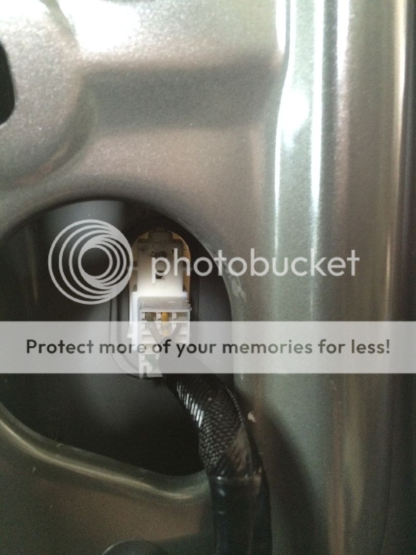
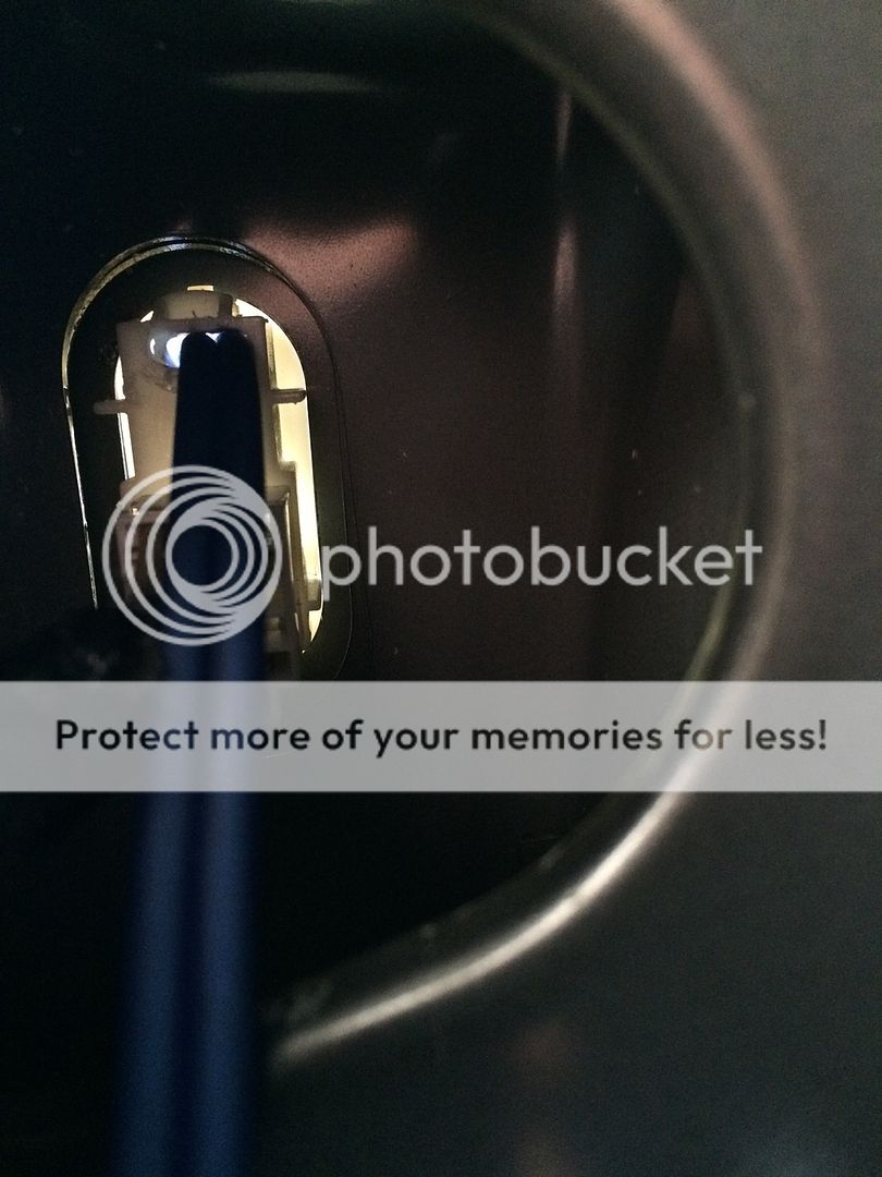
I ran the cables and remote through a hole I found and zip tied it into place.
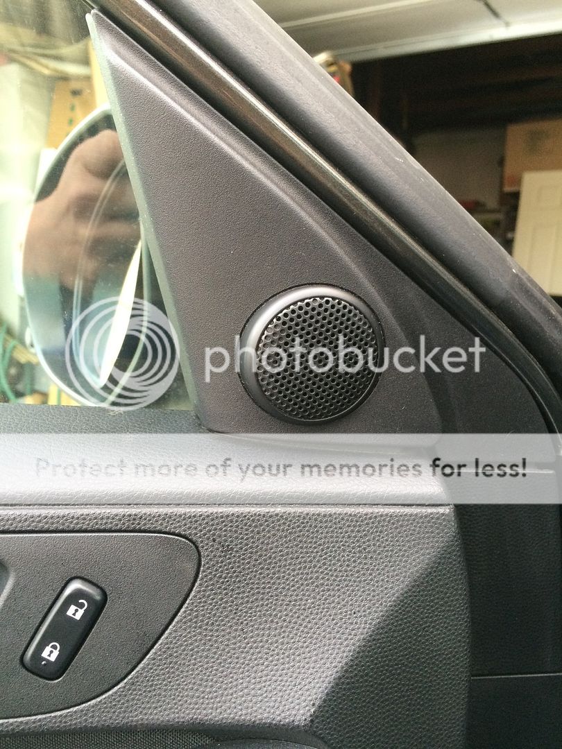
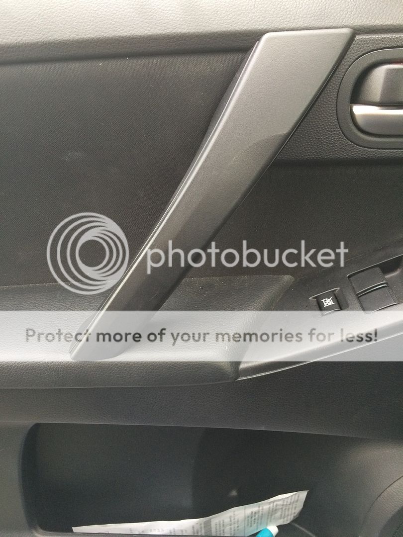
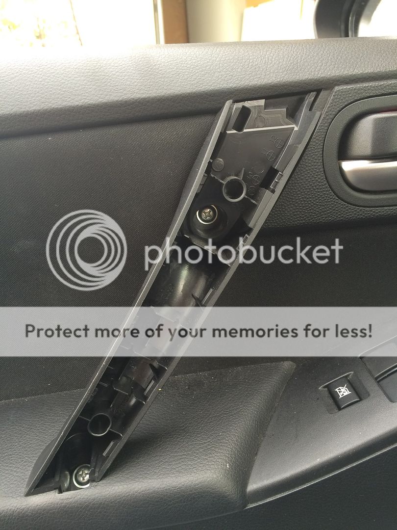
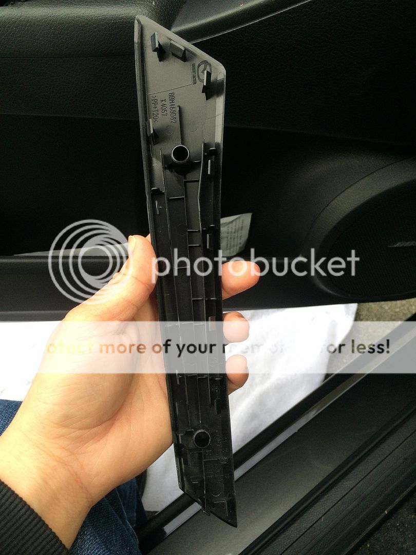
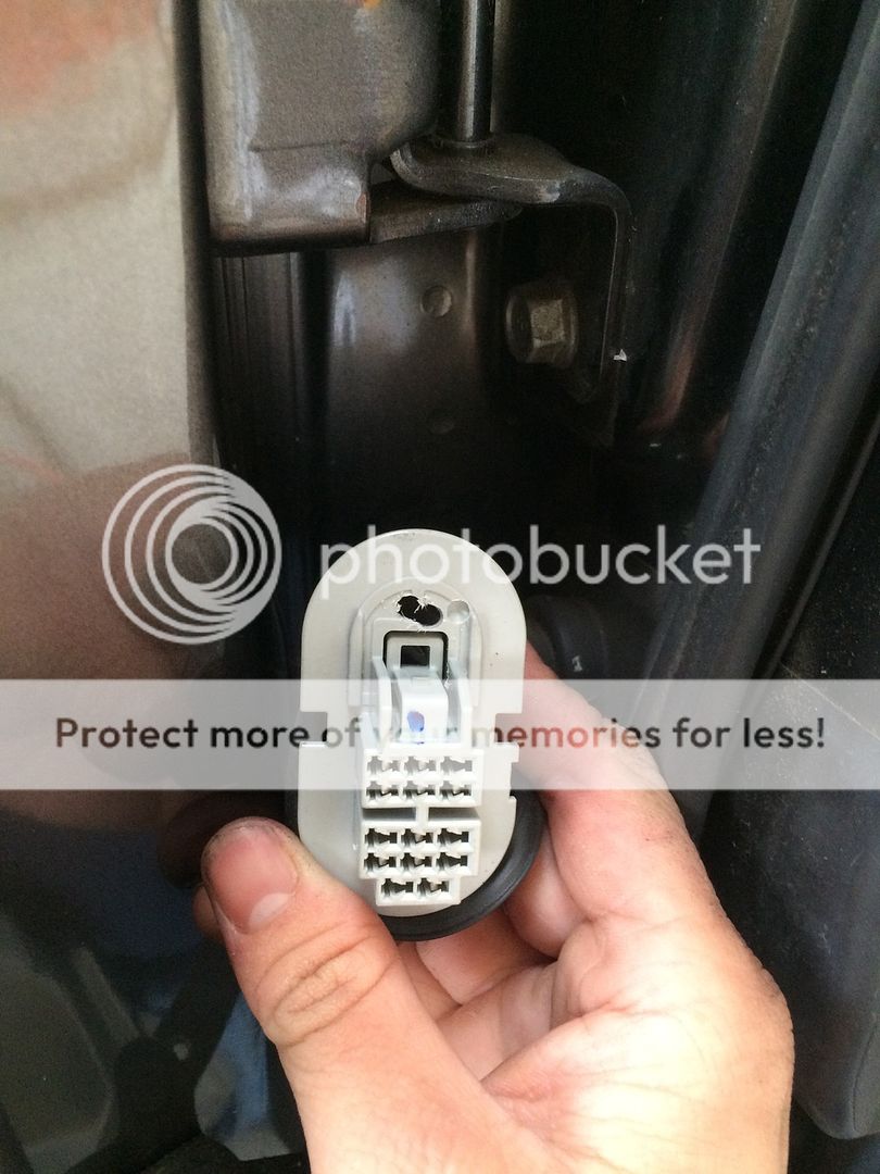
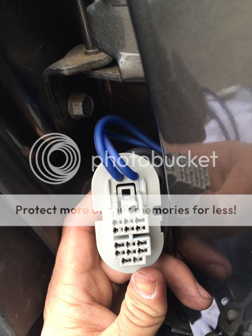
I then ran them under the carpet to the kick panel and under the door sill to the back. To do this, I needed to remove the kick panel and door sill. The kick panel has a simple pin holding it in place. Pull the center dot out and the whole thing will follow. This picture is after I ran the new speaker wire from the door.
Remove the door sill by gently and firmly pulling it up. Next, move the kick panel. Becareful. You'll need to wrestle the rubber off of a hook attached to the kick panel and pull the kick panel along the door sills trajectory. I broke my driver's side kick panel.
Power wire install
Tools:
Philips screw driver
Power drill
7/16 drill bit
*another drill bit will be needed and listed when I find one for another job
12mm socket
10mm socket
Ratchet
Proper fitting rubber grommet (I just randomly found one that fit)
Pam spray (for lube on wire through grommet)
Zipties
Remove the neg battery terminal and secure it in a way that it won't bounce back to original position. I'm not going to pic this because if you don't know how to do this, you shouldn't be installing your own system.
The battery box has a slight opening on the left of it that will allow your cable to slide though with out having to hack the battery box. You will need to attach the O-ring terminal like this in order to do this.
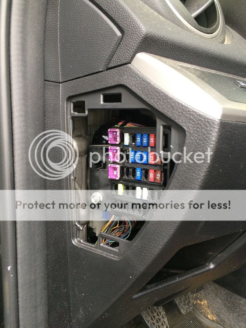
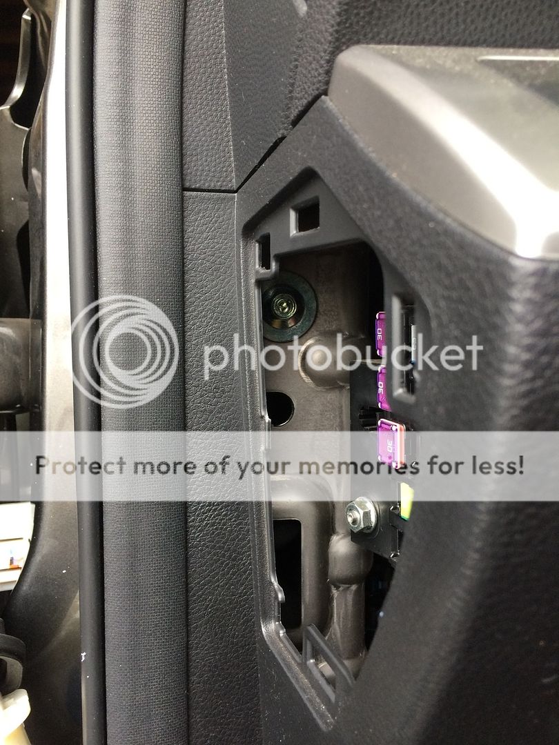
I left the fuse out of my fuse box so that I don't have to worry it being a live wire while the power wire is sitting for actual usage.
Next you will need to drill through the firewall. The place you'll need to drill through is where the Speed3's have that rubber/plastic disc.
For the sedan, it's a solid firewall with no where to run a stray wire. I have heard of people who own an automatic 3 and can run an 8AWG through a rubber boot that runs along the steering column or the place where the clutch goes. Unfortunately this isn't possible for us, but it's better we go through the firewall anyway. The power wire for the original Bose system is on the right side anyway and you want to always run the RCAs where large power wire aren't. Whine can seep into the audio system that you can't eiminate if these 2 wires are next to each other.
To get to this desired spot you will need to remove the glove box. The glove box door is held in place by clips. If you run your hands along the door downwards, you'll find a nice grip and firmly pull. IIRC, there are 4 clips and a 5th one will need to be unhooked on the right. You will see this lonely 5th hook without even attempting this removal.
(Will insert pic later)
Next, there are 2 screws holding the glove box securely.
(Will insert pic later)
(Will insert pic later)
Before continuing, remove the kick panel and door sill. Now you will pull the glove box towards the seat. You should notice the rubber seal on the right that runs all along the door opening.
(Will insert pic later)
There will be a wires that's attached to some lighting inside the glovebox and to the bottom of the glove box for some kind of ambient lighting system. The ambient lighting at the bottom has 2 clips you can unattach easily. The glovebox light will need to be unscrewed.
Here's the preferred area for you to drill.
(Will insert pic later)
Voila! Entry into the engine bay from your cabin. Put a rubber grommet that's nice and snug for your wire and small enough for your hole. You will use Pam cooking grease that's lightly applied to your fingers to get the wire through the grommet. Feed the wire from your engine bay. Mark an area on the wire with eletrical tape to determine a stopping point. You will need just enough to attach to your fuse box.
I will find a better place for my power wire and fuse box. I'm not happy with how much wire is just in mid air, even though it's secured extremely tightly in place. This is where I will use the undetermine drill bit mentioned earlier. I will drill holes somewhere along the edge to zip tie the wire and fuse box. Amp kits predetermine the distance for the fuse box and can limit where you place the fuse box. The fuse box should always be close to the battery. IIRC, 18 inches is the max distance from the battery.
This is how I reran my wire. I removed two plastic screws that hold something and I just ran zipties to hold my wire down and whatever those screws were holding.
Now run the power wire the same way you ran your RCAs on the opposite side.
Last edited: