2013 Mazda5
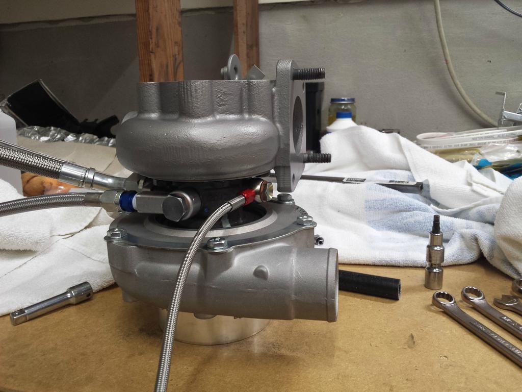
GT2871R
Other stuff
Apologies if this doesn't "flow" coherently as a single post, I collected all the individual updates I've been giving into one post. I'm going to keep all the updates here going forward.
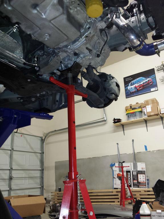
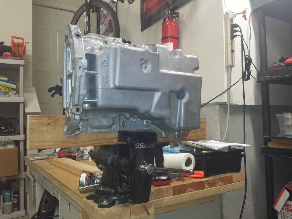
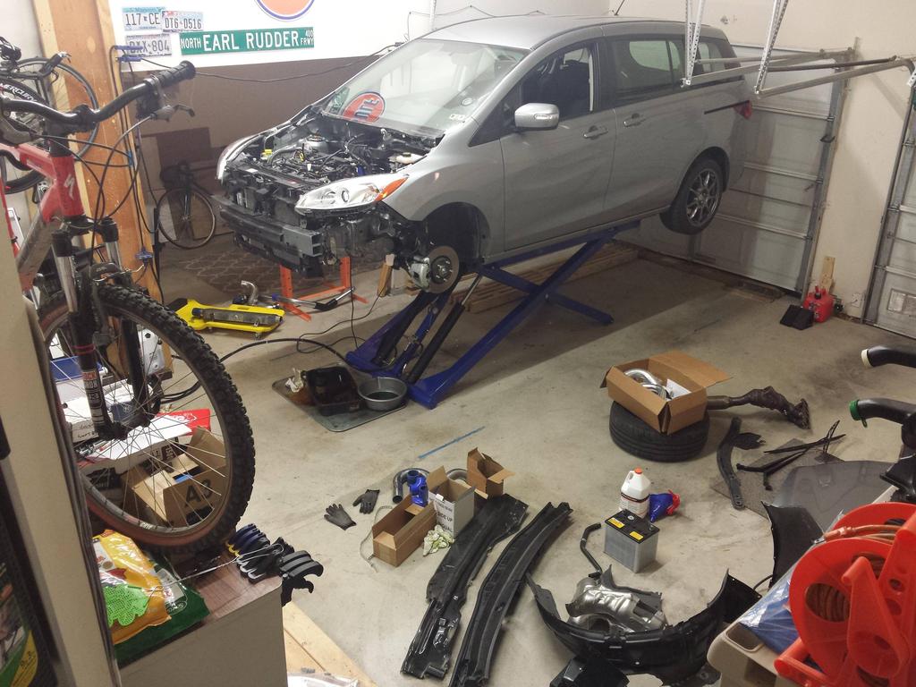
Started yesterday (July 12, 2014) morning with disassembly, things went smoothly, this car is put together very straightforward.
Lunch break. Haven't run into any unexpected problems yet, so morale is still high. The stock manifold and "downpipe" are quite large and difficult to get out. I'm going to need to unbolt and remove the cowl to get it out the rest of the way. I've got the RMM and PMM disconnected, the engine is down and forward, and I still don't have clearance. MS3 people never get to b**** about how hard it is to get a dp or manifold out, ever again, lol.
I got the manifold out in about 2 minutes after taking the cowl off. Should have just started with that, it was easy.
Done for the night, a solid 7am to 9pm workday (45min lunch).
Time consuming tasks accomplished today:
1. Manifold removal
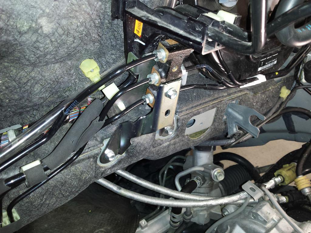
2. Brake distribution block relocation / bracket modification
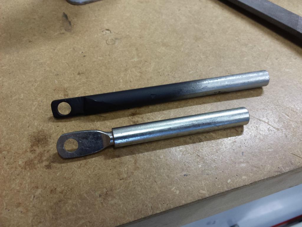
3. Shifter cable bracket relocation / modification
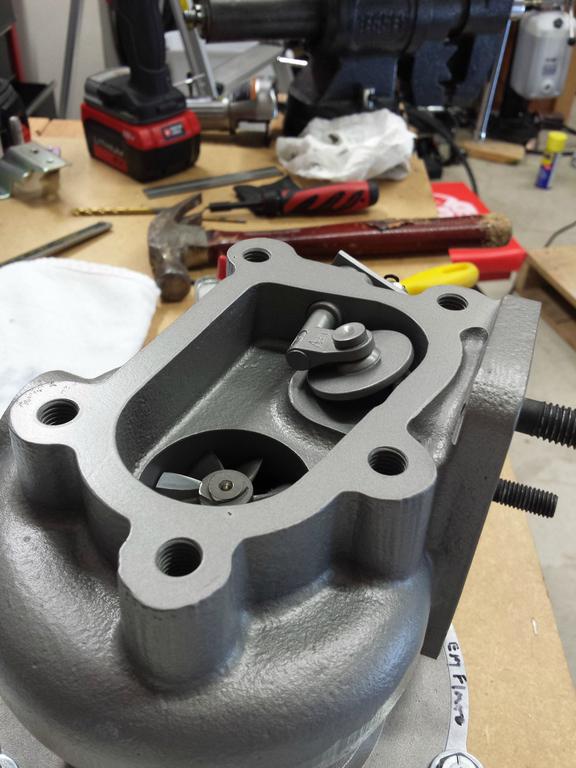
4. Oil feed source / oil filter housing removal and installation (this was the unexpected difficulty)
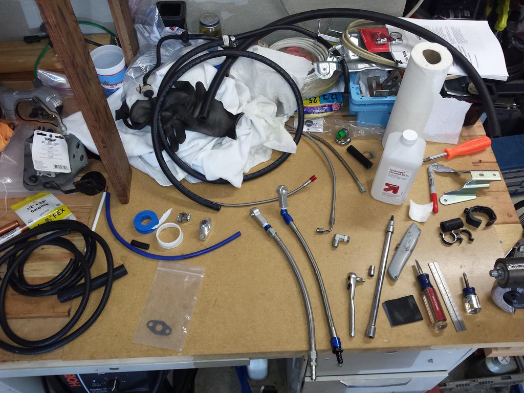
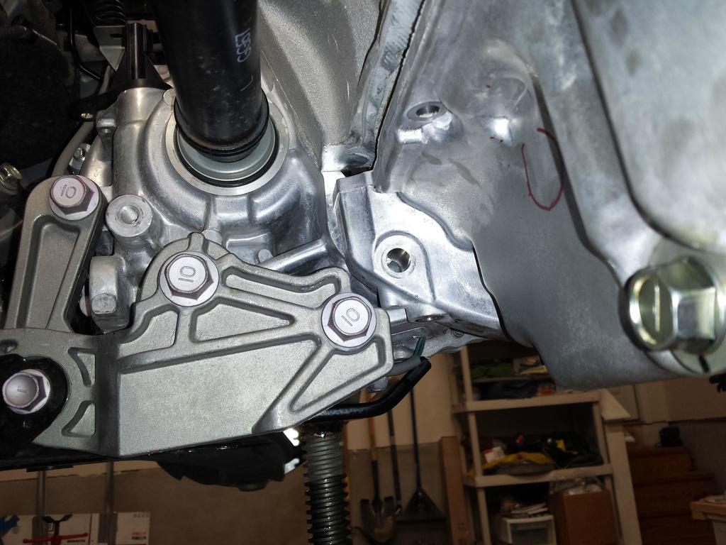
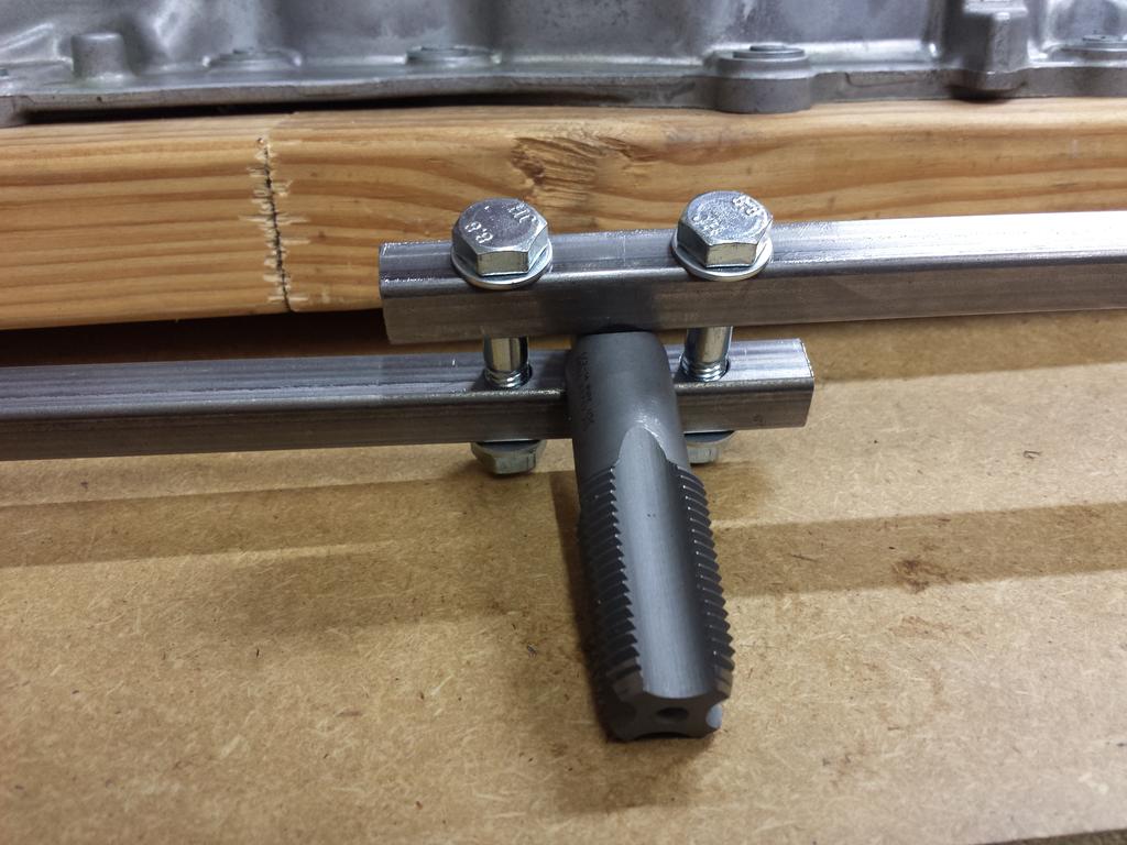
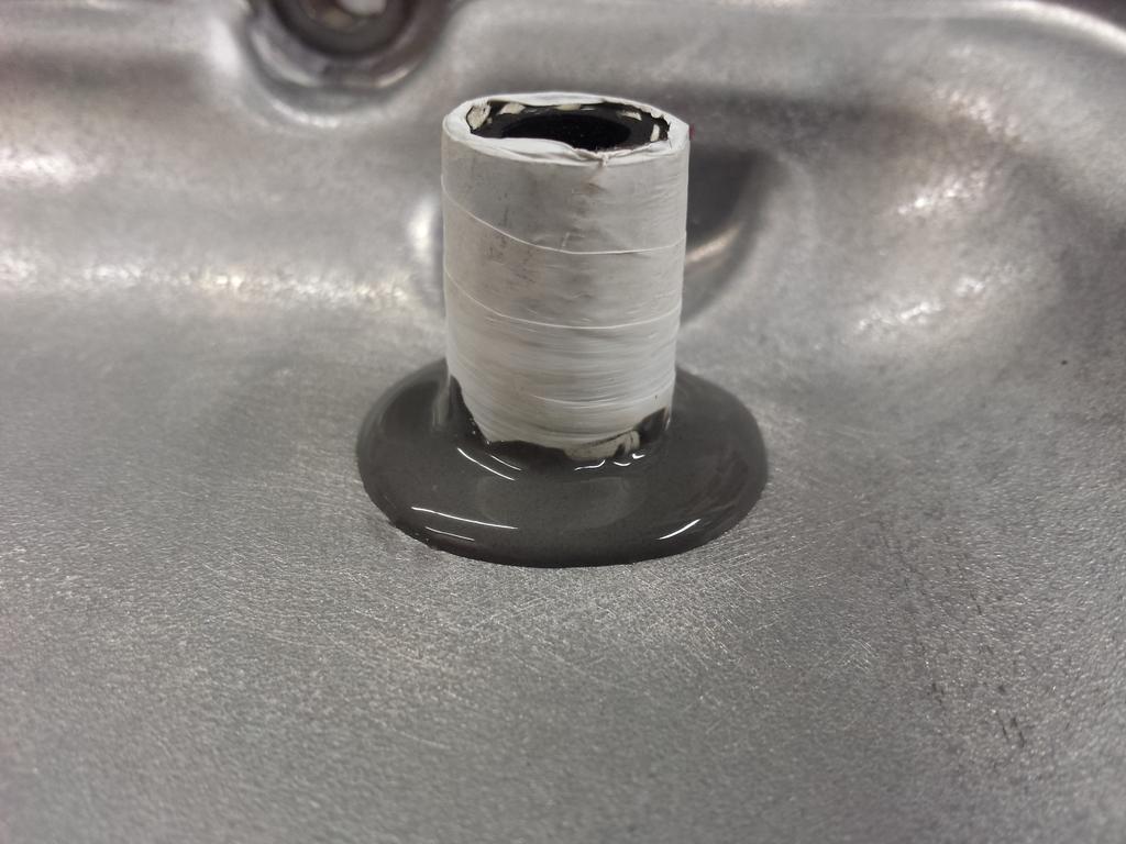
I used a Tee fitting on the oil pressure switch as planned. Removed the oil filter housing no problem. Had to loosen and rotate the oil filter cooler a few degrees (not to much such that it would leak) to get clearance to the front for the switch. But then I had to be mindful that the lower NPT to AN fitting had tight clearance to a protruding ear on the block casting.
Then the main issue was that the Tee fitting obscured the top right bolt on re-installation. I had to take the Tee fitting out (many times) and re-wrap with more Teflon tape so that the Tee fitting wouldn't screw in so far. Even so, clearance to that bolt was tight, and involved a combination of using a box wrench 5degrees at a time, and a 10mm 1/4" socket that still didn't quite grab the socket fully. All in all, I probably went back and forth between the car and workbench about 30 times test fitting and attempting to install the thing before finally getting it working.
If I had to do it again, I'd use a Tee fitting where the fitting connects to the housing (the male fitting) on the top of the "T", instead of the base. Basically, so that the switch and AN fitting were on the right and bottom, instead of the top and bottom like they are now.
Mazdaspeed3 guys need to stop bitching about how hard it is to get a down pipe out of their cars:
The cowl comes out easily and give tons of room:
Test fitting the intake:
Done for the night:
Sunday, July 13
Nearly 14 hours straight yesterday was too much, and I was unmotivated and lazy in the morning today. Didn't really get started until noon, then took a long break from 3pm to 6pm, so I didn't get much done today. IC mounting, IC piping finished, modified heater core hoses. IC mounting and heater core hose modification/routing required more trips to Home Depot and the auto parts store than I would have liked. Hose routing was one thing I couldn't be 100% prepared for without tearing into the car.
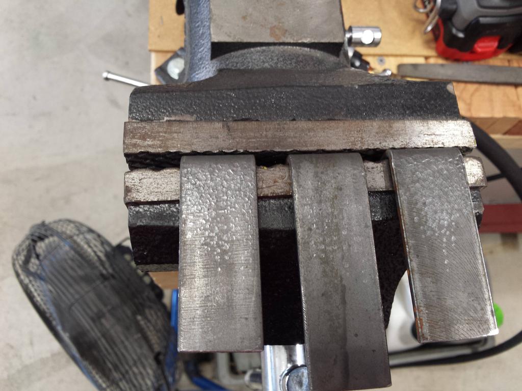
"Artisan" hand-hammered intercooler brackets for sale... Old-world craftsmanship, only $50 each!
(yes the middle one is supposed to be longer, due to the curvature of the bumper)
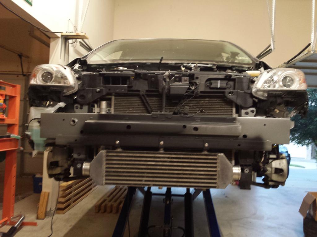
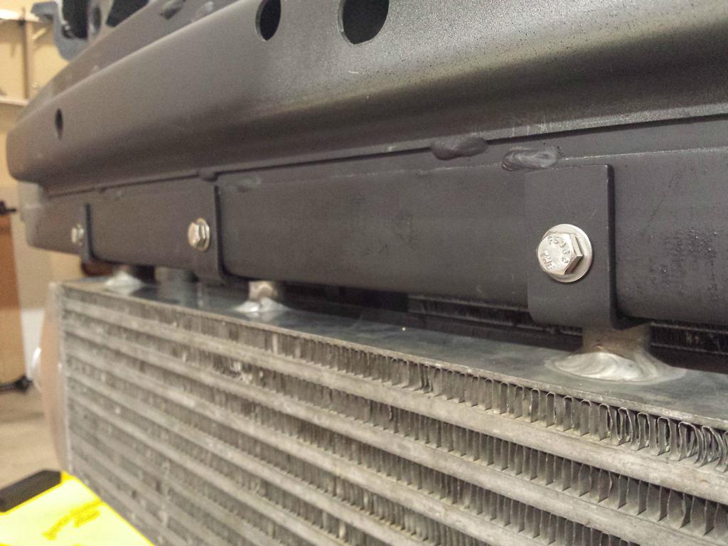
IC mounted:
Close up of the mounts I spent too long making. Double shear mounting and stainless hardware:
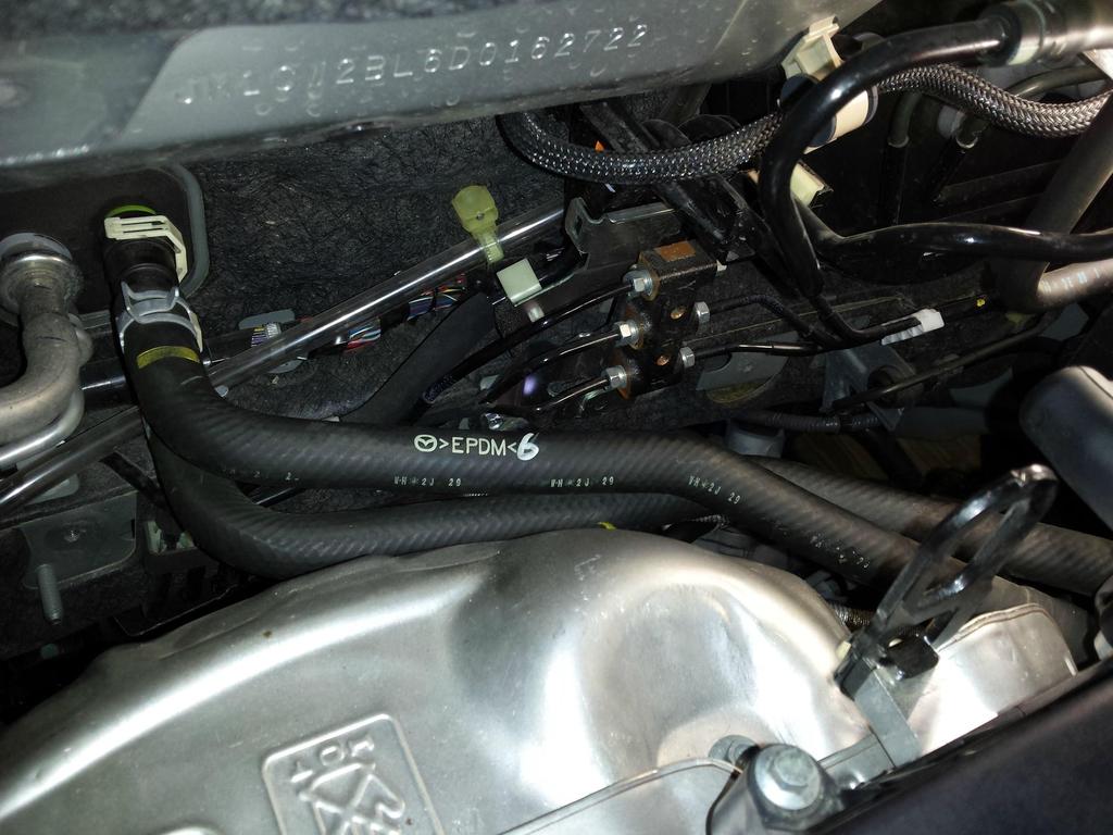
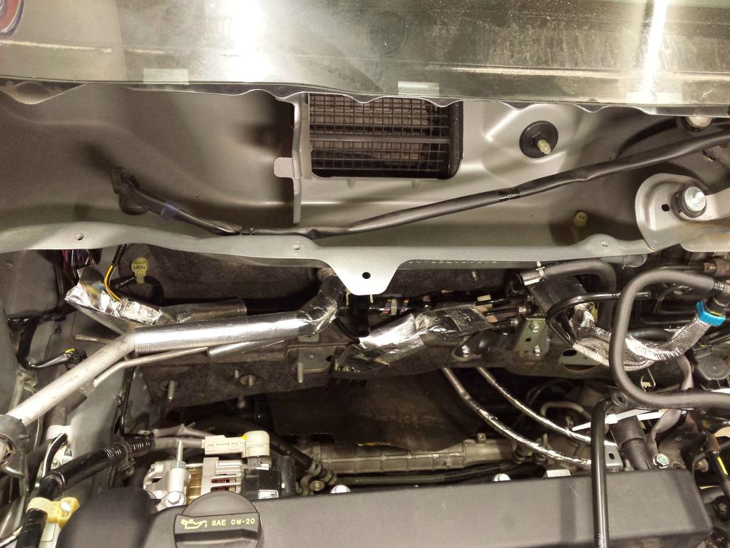
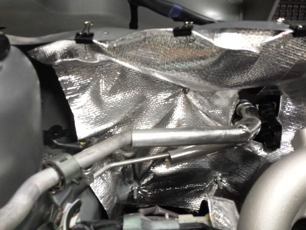
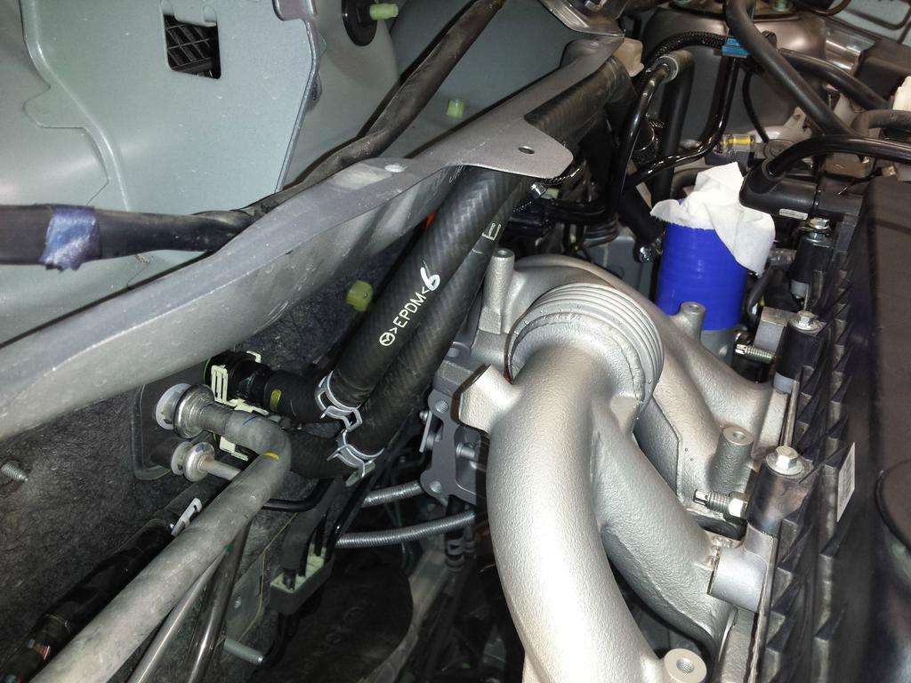
Heater core hoses viewed from the top. This took a while to find the exact routing I liked best. The "standard" routing for them in a NA FI build didn't work on my car b/c I have a brake line distribution block in the way of the normal path. Yes, they will get a shitload of heat shielding.

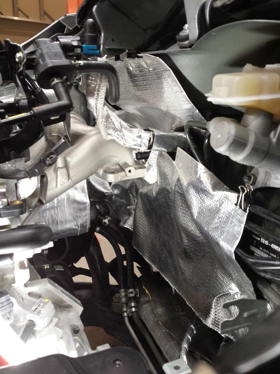
Heater core lines from passenger side.
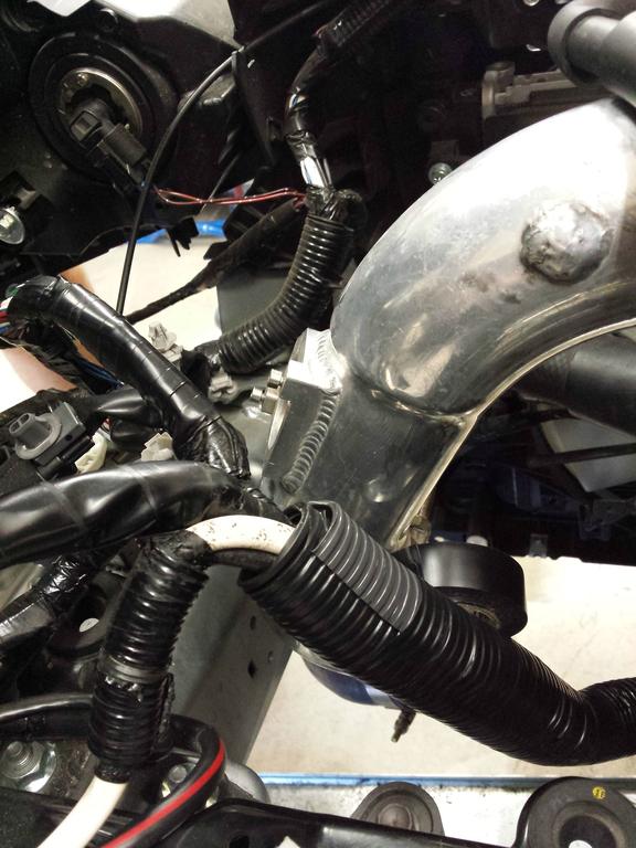
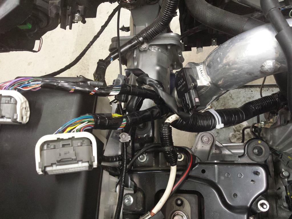
From the drivers side:

More to come tomorrow...
GT2871R
Other stuff
Apologies if this doesn't "flow" coherently as a single post, I collected all the individual updates I've been giving into one post. I'm going to keep all the updates here going forward.
Started yesterday (July 12, 2014) morning with disassembly, things went smoothly, this car is put together very straightforward.
Lunch break. Haven't run into any unexpected problems yet, so morale is still high. The stock manifold and "downpipe" are quite large and difficult to get out. I'm going to need to unbolt and remove the cowl to get it out the rest of the way. I've got the RMM and PMM disconnected, the engine is down and forward, and I still don't have clearance. MS3 people never get to b**** about how hard it is to get a dp or manifold out, ever again, lol.
I got the manifold out in about 2 minutes after taking the cowl off. Should have just started with that, it was easy.
Done for the night, a solid 7am to 9pm workday (45min lunch).
Time consuming tasks accomplished today:
1. Manifold removal
2. Brake distribution block relocation / bracket modification
3. Shifter cable bracket relocation / modification
4. Oil feed source / oil filter housing removal and installation (this was the unexpected difficulty)
I used a Tee fitting on the oil pressure switch as planned. Removed the oil filter housing no problem. Had to loosen and rotate the oil filter cooler a few degrees (not to much such that it would leak) to get clearance to the front for the switch. But then I had to be mindful that the lower NPT to AN fitting had tight clearance to a protruding ear on the block casting.
Then the main issue was that the Tee fitting obscured the top right bolt on re-installation. I had to take the Tee fitting out (many times) and re-wrap with more Teflon tape so that the Tee fitting wouldn't screw in so far. Even so, clearance to that bolt was tight, and involved a combination of using a box wrench 5degrees at a time, and a 10mm 1/4" socket that still didn't quite grab the socket fully. All in all, I probably went back and forth between the car and workbench about 30 times test fitting and attempting to install the thing before finally getting it working.
If I had to do it again, I'd use a Tee fitting where the fitting connects to the housing (the male fitting) on the top of the "T", instead of the base. Basically, so that the switch and AN fitting were on the right and bottom, instead of the top and bottom like they are now.
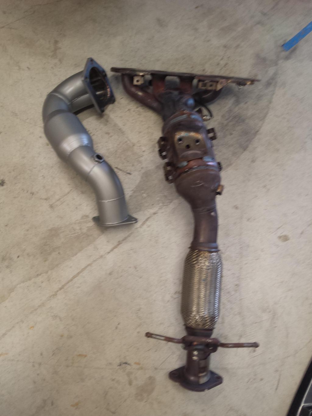
Mazdaspeed3 guys need to stop bitching about how hard it is to get a down pipe out of their cars:
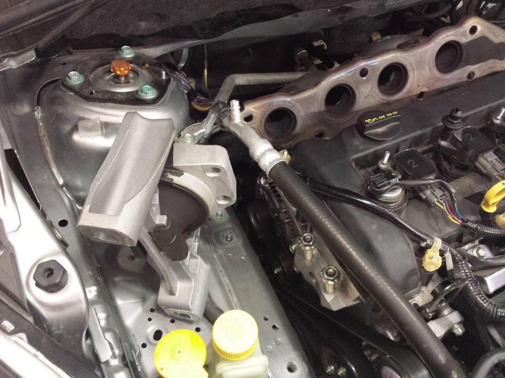
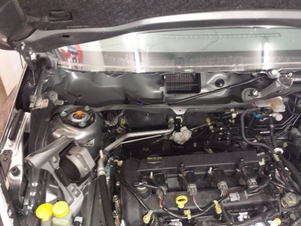
The cowl comes out easily and give tons of room:
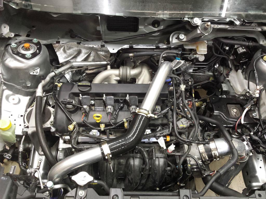
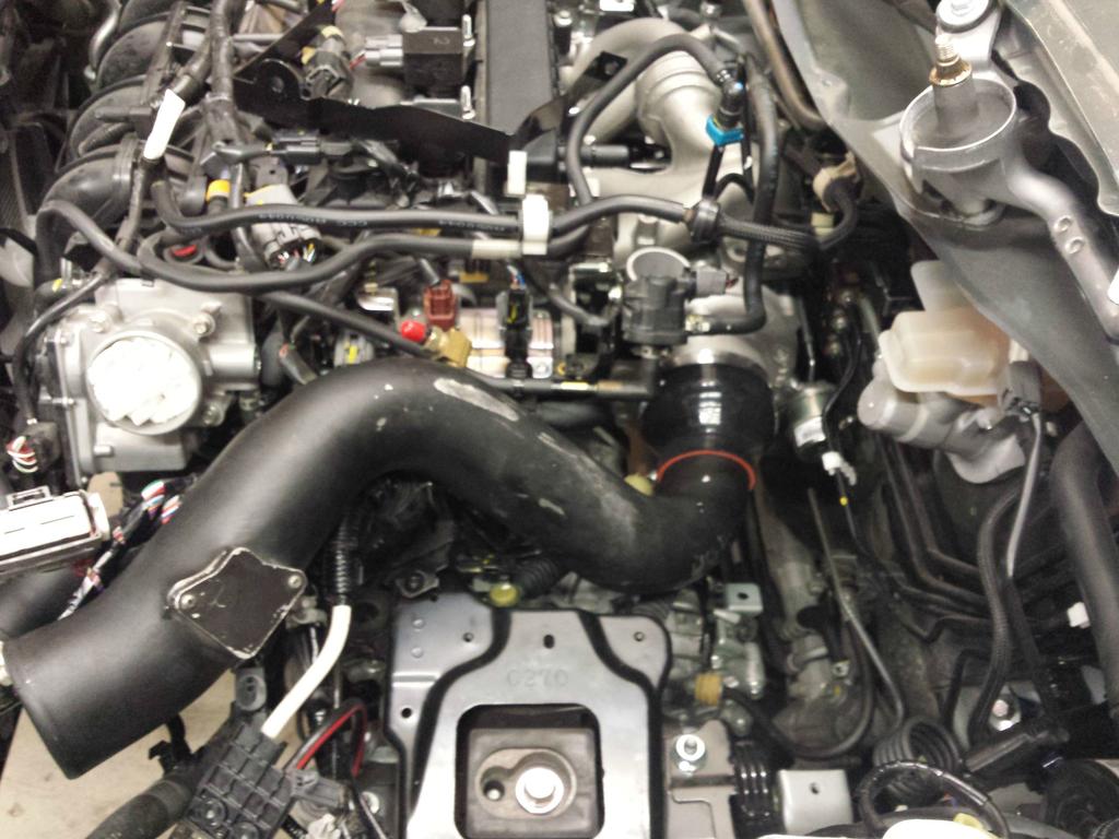
Test fitting the intake:
Done for the night:
Sunday, July 13
Nearly 14 hours straight yesterday was too much, and I was unmotivated and lazy in the morning today. Didn't really get started until noon, then took a long break from 3pm to 6pm, so I didn't get much done today. IC mounting, IC piping finished, modified heater core hoses. IC mounting and heater core hose modification/routing required more trips to Home Depot and the auto parts store than I would have liked. Hose routing was one thing I couldn't be 100% prepared for without tearing into the car.
"Artisan" hand-hammered intercooler brackets for sale... Old-world craftsmanship, only $50 each!
(yes the middle one is supposed to be longer, due to the curvature of the bumper)
IC mounted:
Close up of the mounts I spent too long making. Double shear mounting and stainless hardware:
Heater core hoses viewed from the top. This took a while to find the exact routing I liked best. The "standard" routing for them in a NA FI build didn't work on my car b/c I have a brake line distribution block in the way of the normal path. Yes, they will get a shitload of heat shielding.
Heater core lines from passenger side.
From the drivers side:
More to come tomorrow...