Why no sticky? Next time I start having issues with my AC switch, I will be diving in behind my stereo and permanently fixing it.

You are using an out of date browser. It may not display this or other websites correctly.
You should upgrade or use an alternative browser.
You should upgrade or use an alternative browser.
Guide Permanently fix the "no A/C on fan speed 2/3" problem
- Thread starter CheeseHelmet
- Start date
protogenius
Member
- :
- protoge 5 2002
Dear Cheese Helmet,
I followed your directions today to fix my AC that has been crapping out over the last 2 years. Thank you for making it so easy. It is working fine now. Now I just need to change an O2 sensor.
I followed your directions today to fix my AC that has been crapping out over the last 2 years. Thank you for making it so easy. It is working fine now. Now I just need to change an O2 sensor.
Fixed mine! Feels good to stay cool.
Hell yeah! I had been driving with a non existent 3 and flicker 2 for years. Then 2 completely failed and 4 was starting to flicker. Every single position works now!
- :
- Protege5 2003
Hell yeah! I had been driving with a non existent 3 and flicker 2 for years. Then 2 completely failed and 4 was starting to flicker. Every single position works now!
If 4 was giving you problems you need to check the power wires and the switch. See my posts here:
http://www.mazdas247.com/forum/show...3-A-C-PART-2&p=5647383&viewfull=1#post5647383
and
http://www.mazdas247.com/forum/show...3-A-C-PART-2&p=5672270&viewfull=1#post5672270
In position 4 the wiring is 12V -> blower -> big wire (1) -> switch position 4 -> switch wipers (internal) -> switch ground -> big wire (2) -> "ground". (Where it is "ground" because the voltages indicate that there may be a diode in the path, raising the sense voltage to 0.45 instead of 0 at position 1.) For position 4 to flicker there needs to be enough resistance on the main current path between the blower and "ground", to raise the sensor wire voltage about 0.2V, and the only place that could be is in the switch, one or both of the big wires, or the connectors where these things come together. This cannot be a problem in the resistor pack under the glove box because the wire for position 4 diverts the blower current before it enters the resistor pack.
Both my fix and the one in this thread will keep the compressor working as these sorts resistances increase, but more and more heat will be generated at the high resistance spots in the circuit until eventually something melts (or worst case, catches fire).
..., but more and more heat will be generated at the high resistance spots in the circuit until eventually something melts (or worst case, catches fire).
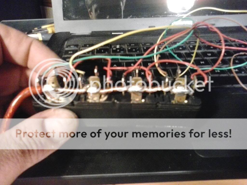
That's why I did this,...
My fan switch only controls the relays,... there's no power through it.
Last edited:
- :
- Protege5 2003
That's why I did this,...
My fan switch only controls the relays,... there's no power through it.
Interesting idea - with the switch just shifting current to relays the switch should never carry a significant load and so it shouldn't ever burn up.
That looks like one substantial ground wire!
The picture is a little out of focus so hard to tell. Does that reuse the existing wires from the resistor pack to the load side of the relays, and new wires from the console switch to the control side?
Where did you mount the relays? Hopefully some place where nothing conducting can touch any of that wiring. If your switch is set to off so that the load sides of the relays are open there will be 12V between the ground and the wires that run to the resistor pack. The wire for position #4 has only the internal resistance of the blower to limit the current. I don't recall what the maximum current through the blower is exactly, but it is on the order of 10A, so there might be quite a show if anything ever shorted the #4 wire lead to the ground wire or any bare metal nearby. In the factory harness all the conducting parts are inside the plastic connectors so that that sort of short cannot occur.
Does that reuse the existing wires from the resistor pack to the load side of the relays, and new wires from the console switch to the control side ?
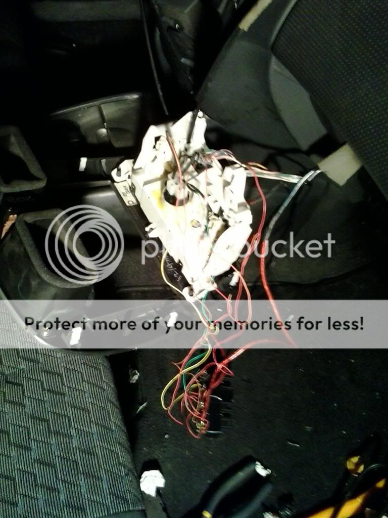
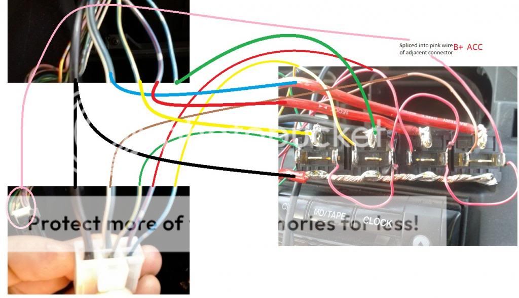
Here's a picture that shows the wiring,...
Where did you mount the relays?
I didn't bother mounting the relays,... I just rolled everything up and stuffed them under the dash,... It doesn't matter,... If anything shorts out the fan starts blowing,... Its not a dead short the switching is done in the ground wire after the load.
The only positive wire is used to power the relays and I stole that from a pink wire from under the dash,... if that one shorts out, it blows one of the dash fuses,...I forget which one.
Last edited:
Andreas1543
Member
- :
- Mazda Tribute
Hi all, im looking for a A/C switch like the on/off button inside the car, i have a Mazda Tribute 2005 2,3 and the switch broke, can anyone help?
Also when the A/C is on the fans run all the time, is that normal? on other cars the fans go on and off!!
Thanks for helping with this
Also when the A/C is on the fans run all the time, is that normal? on other cars the fans go on and off!!
Thanks for helping with this
fiercekrypton
Member
- :
- Mazda Protege5 02
seems like a lot of risk just to gain access to the coveted "2" speed haha, I have the rest... usually.
I read all the threads on this subject "A/C flickering".
Personally, I only experienced it on speed 2 mostly when it's very hot outside and I just started the car. I'll just move to speed 3 and few minutes later go back to speed 2. I feel the most comfortable with speed 2 for 90% of the time while driving day to day.
Regardless, I'm going to do this today and report later.
ok, here is the results after doing this and driving for a few days.
positive: The A/C has been on solid, not even a slight flicker at any speed. nice and cold.
but it really hasn't been hot like I mentioned on my previous post, when it usually cuts-off at #2 speed or it may be a coincidence the A/C has been on solid.
negative: I felt the engine was about to shut-off on me.
So my Pro5 has an automatic transmission and never had the engine shut-off or stall out on me, so when I felt it was about I thought it was odd.
After driving some more I noticed it was only trying to stall out as I was coming to a compltere stop (redlight/ stop sign). I was looking at my scangauge and tach and the RPMs were dipping to the low 600s.
Then the RPMS will jump back up to 750ish at idle and it was smooth and while accelerating, only stalling on coming to a stop. The same thing was going on with the A/C off, so that didn't make any difference.
The only difference in doing this was the following:
Materials:
I have a pack of 500 resistors and oddly enough I didn't have any of these 2 sizes so I used a 510ohm instead of the 470, and a 220ohm instead of the 200.
I am no expert, but I don't think those small difference in values will cause the engine to stumble while coming to a stop.
positive: The A/C has been on solid, not even a slight flicker at any speed. nice and cold.
but it really hasn't been hot like I mentioned on my previous post, when it usually cuts-off at #2 speed or it may be a coincidence the A/C has been on solid.
negative: I felt the engine was about to shut-off on me.
So my Pro5 has an automatic transmission and never had the engine shut-off or stall out on me, so when I felt it was about I thought it was odd.
After driving some more I noticed it was only trying to stall out as I was coming to a compltere stop (redlight/ stop sign). I was looking at my scangauge and tach and the RPMs were dipping to the low 600s.
Then the RPMS will jump back up to 750ish at idle and it was smooth and while accelerating, only stalling on coming to a stop. The same thing was going on with the A/C off, so that didn't make any difference.
The only difference in doing this was the following:
Materials:
- 1x 470 Ohm resistor (1/4W or greater)
- 1x 200 Ohm resistor (1/4W or greater)
I have a pack of 500 resistors and oddly enough I didn't have any of these 2 sizes so I used a 510ohm instead of the 470, and a 220ohm instead of the 200.
I am no expert, but I don't think those small difference in values will cause the engine to stumble while coming to a stop.
YELLOWMAZDAPR5
Member
- :
- 2002 MAZDA, PROTEGE 5 Turbo
Sub
DILYSI Dave
Member
- :
- P5
I haven't done it, but I'm pretty confident it would work. I'd recommend using a 2K resistor to match the performance of the solution I posted. Here are the simulated results with R48 being replaced with a 2K resistor:
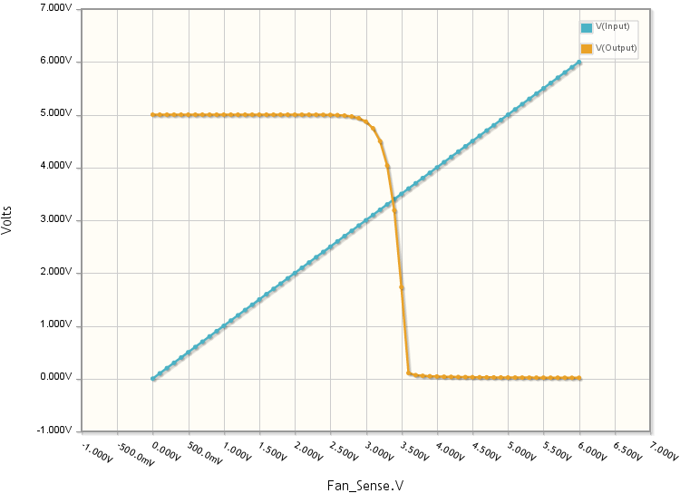
The result is pretty much identical and there's no hacky wiring
The resistors on that board are all surface mount, but there's plenty of room to fit a through-hole resistor if you stand it up. Just make sure to glue it in place so it doesn't vibrate itself loose!
")
So I really like the idea of the PCB solution versus the spliced wiring. Where does this PCB live? I assume it's inside the housing that the black plug plugs into?
DILYSI Dave
Member
- :
- P5
Ok, got the PCB out. The write up said 4.7k, the response here said 2k for the R48 resistor. I assume 2k is the revised value, but wanted to confirm.
DILYSI Dave
Member
- :
- P5
Ok, got the PCB out. The write up said 4.7k, the response here said 2k for the R48 resistor. I assume 2k is the revised value, but wanted to confirm.
Kinda talking to myself here, but for future reference for anyone else, the 2k did the trick.
All told a simple enough fix. Biggest hang up when you do it is that one of the control cables passes over a cover that has to come off, and the control cable is snapped into this one-way doohickey that won't allow it to come out. I figured out that snap ring pliers will open up the lock though and allow the cable to release. Beyond that, all pretty straightforward.