
You are using an out of date browser. It may not display this or other websites correctly.
You should upgrade or use an alternative browser.
You should upgrade or use an alternative browser.
Guide Permanently fix the "no A/C on fan speed 2/3" problem
- Thread starter CheeseHelmet
- Start date
Although, now that you mention it...a year back I was in there for something else and noticed how hot the a/c wires were. too hot to be proper. I remember thinking I was going to have to deal with that or that likely is the cause for the a/c failure. I dont remember what wires they were, only that they were in the vicinity of the a/c switch.
If you take apart and clean your switch (which I believe you should),... open it carefully over a box or something,... it's spring loaded and the ball bearing from the backside of the switch went flying on me. (luckily I found it on the garage floor). The bearing allows it to 'click' into the different fan speeds.
Getting the switch out and apart is a little tricky and even the lock nut on the back of the switch is cheap ass plastic. Mine broke so I hot glued it back into place to allow me to more easily remove it next time,... I'm sure there will be a next time. (my AC light will start to flash again telling me it's time for another cleaning)
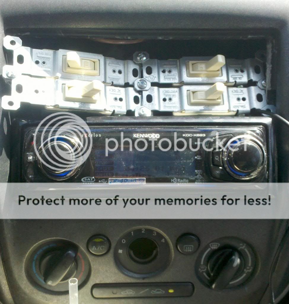
Or of course you could just do this:
Getting the switch out and apart is a little tricky and even the lock nut on the back of the switch is cheap ass plastic. Mine broke so I hot glued it back into place to allow me to more easily remove it next time,... I'm sure there will be a next time. (my AC light will start to flash again telling me it's time for another cleaning)
Or of course you could just do this:
Yea,... the switch picture is kind of a joke but you gotta love the guys ingenuity and his awesome ghetto approach.
If it were me, and I wanted to get carried away with a fix,... I would add four 30 amp relays to the system and have the fan switch control the relays with about 20 milliamps of power running through the switch instead of 12 full amps.
I say DEFINITELY take apart your switch,... clean it and sand it shiny again,... then put a dab of grease on it.
I suggest remove the switch and take it to a comfortable work space where you can sit down and carefully take your time disassembling it. It's a flimsy ass piece of crap and you'll have no blow at all if you break it or lose some pieces. (although you could 'jumper' the fat black wire to one of the other wires in the connector to have one 'always on' fan speed till you find a replacement)
Last edited:
- :
- 2010 Mazda5 GT
I did it last night and no change, at all! I'm pretty frustrated at this point since i cut and soldered all the lines, it wont be neat and clean and easy to do it again, maybe I got something backwards but I don't think so.
The first couple of attempts with this fix didn't work for me. It turned out to be the butt connectors I purchased from RS. They were slightly too big and didn't make good connections. I winded up just splicing them and reinforcing with heat shrink and electrical tape. That did the trick.
kosteniuks17
Member
- :
- Mazda Protege5 2003
Hey North, are you sure you cut the blue and yellow wire that is from the lower wire connector or the top bundle? the top bundle connects to the fan switch mechanism, the one you should be cutting is the connector that is below that bundle. It has fairly smaller wires to it. You can see it in the picture given by the follow-to. Its the lower white and black connection.
Hey North, are you sure you cut the blue and yellow wire that is from the lower wire connector or the top bundle? the top bundle connects to the fan switch mechanism, the one you should be cutting is the connector that is below that bundle. It has fairly smaller wires to it. You can see it in the picture given by the follow-to. Its the lower white and black connection.
"White and Black connection" ? I absolutely used the wiring harness with the black plastic connector that is below fan speed control switch. It is a blue and yellow wire, correct? I also used (on that same wire harness)the black wire for the ground.
Did I do this correctly? I believe so.
I have attached pics from what is the white connector that plugs into the the fan sped control switch. Not to be confused with the black harness I did the follow-to with. I posted these switch pictures to show the damage done on the harness and was wondering if this by chance is the real problem with MY VEHICLE.
.jpg")
.jpg")
.jpg")
i wish i could understand the diagrams cheesehelmet's linked to -_-
I'm thinking about doing the resistor thing but i'm a bit concerned about the switch heating up problem. I like the light switch idea... i'd feel cool with all those switches. I also like the overdone adding in relays idea since i don't want to melt anything in the future.
And then sometimes i just wish i didn't have an AC so people would quit asking me to turn it on when i don't want to...
I have a spare switch here somewhere, let's take it apart and look at it shall we-
-
sorry if it is hard to see but from what I can tell, the thick black wire(GND) has melted off some of the protective sheathing and also started a bit of green colored corrosion on the bare copper wire. Also it has melted a hole through the white plastic harness connector, if you look real close...you can see that two of the copper strands have actually broken . This i am sure is causing a resistance issue. Don't know what I'm going to do to repair it yet. maybe i'll see if I can get a better looking harness down at the bone-yard and solder it in maybe. not sure yet.
That plastic connector itself isn't very important. You could remove the individual terminals from the plastic holder,... clean them all up,... replace the terminal end on the fat black wire (trimming an inch or so off the end of the wire) and just plug them onto their respective terminals on the back of the switch.
There really is no danger of any kind of short within the connector itself,... if they do touch each other, the fan just turns on. The fat black wire should never touch ground though because that is B+ from the battery and you will blow a fuse.
There really is no danger of any kind of short within the connector itself,... if they do touch each other, the fan just turns on. The fat black wire should never touch ground though because that is B+ from the battery and you will blow a fuse.
Installshield 2
Gothenburg Superiority
I'm torn on what to do with this...Mine has been getting just a little worse year after year for 11 years...As it finally warmed up in my area...I no longer have speeds 2 or 3...but 1 and 4 still work fine...2 has been problematic since i bought the car new...3 would 'usually' work, but occasionally flicker if the interior of the car was blazing hot...after 5 minutes or so of speed 4, 3 would then work without a problem...not the case any longer...
So my question is: I know this overall is caused by the PCB for the hvac system, right? I know there is an additional issue caused by corrosion of the fan speed switch, but i've checked mine numerous times and it still seems ok...clean and tight...
If i source a revised PCB...what am i getting? does this control board include a new harness and adapter? As in, does the full unit replace the harness that i'd be hacking in to? Or do i utilize my existing wiring to simply snap into a revised circuit board? Depending on how that works out, i'll probably try this first...and if i mess it up just go source a new board with included wiring...if it doesn't include a replacement wiring lead and connector, i'll probably just find the pcb entirely...
crossover sells the revised unit straight from mazda...its not cheap, but is the exact part number required in the official Mazda TSB about this issue...I may be able to find one locally, but its been a while since i've dug around under my stereo...other than just unclipping the speed switch to see how its doing...
I'm torn on what to do with this...Mine has been getting just a little worse year after year for 11 years...As it finally warmed up in my area...I no longer have speeds 2 or 3...but 1 and 4 still work fine...2 has been problematic since i bought the car new...3 would 'usually' work, but occasionally flicker if the interior of the car was blazing hot...after 5 minutes or so of speed 4, 3 would then work without a problem...not the case any longer...
If your fan switch and connector are tight and clean,... then cheesehelmut's fix should work perfectly for you,... in fact I almost guarantee it. It's fast cheap and easy.
I just don't want people to neglect their switch and try the fix because it may very well not work,... especially if even the fan won't blow.
CheeseHelmet
Member
I did it last night and no change, at all! I'm pretty frustrated at this point since i cut and soldered all the lines, it wont be neat and clean and easy to do it again, maybe I got something backwards but I don't think so.
If everything is working as it was then it sounds like the ground is improperly connected, or you swapped the two resistors. Please take a second look at your wiring.
There really is no danger of any kind of short within the connector itself,... if they do touch each other, the fan just turns on. The fat black wire should never touch ground though because that is B+ from the battery and you will blow a fuse.
That's not true, the fat black wire is ground. The color should give you a hint

[snip]
So my question is: I know this overall is caused by the PCB for the hvac system, right? I know there is an additional issue caused by corrosion of the fan speed switch, but i've checked mine numerous times and it still seems ok...clean and tight...
If i source a revised PCB...what am i getting? does this control board include a new harness and adapter? As in, does the full unit replace the harness that i'd be hacking in to? Or do i utilize my existing wiring to simply snap into a revised circuit board? Depending on how that works out, i'll probably try this first...and if i mess it up just go source a new board with included wiring...if it doesn't include a replacement wiring lead and connector, i'll probably just find the pcb entirely...
crossover sells the revised unit straight from mazda...its not cheap, but is the exact part number required in the official Mazda TSB about this issue...I may be able to find one locally, but its been a while since i've dug around under my stereo...other than just unclipping the speed switch to see how its doing...
It's caused by a combination of a bad control circuit, corrosion inside the switch, and corrosion on the contacts. Like PCB said, there's a good chance that this method will fix the problem for you. Worst-case, you can always remove it. It's not a very invasive process.
This is the first I hear of a TSB for this problem, got a link to more info? I'm curious
That plastic connector itself isn't very important. You could remove the individual terminals from the plastic holder,... clean them all up,... replace the terminal end on the fat black wire (trimming an inch or so off the end of the wire) and just plug them onto their respective terminals on the back of the switch.
There really is no danger of any kind of short within the connector itself,... if they do touch each other, the fan just turns on. The fat black wire should never touch ground though because that is B+ from the battery and you will blow a fuse.
OOOPS (again) I didn't refer to the schematic and went from memory.
The fat black wire is definately ground,... with that being said,... NONE of the wires in the connector matter as far as shorting out to ground. That's all the switch does anyway. (connect one of the fan speeds to ground)

That's not true, the fat black wire is ground. The color should give you a hint
Good point,... I sometimes miss the obvious,... OOOOPS again.
Installshield 2
Gothenburg Superiority
It's caused by a combination of a bad control circuit, corrosion inside the switch, and corrosion on the contacts. Like PCB said, there's a good chance that this method will fix the problem for you. Worst-case, you can always remove it. It's not a very invasive process.
This is the first I hear of a TSB for this problem, got a link to more info? I'm curious
Here you go man:
[h=2]TSB: 07-005/03[/h]look for that listing on ed's FAQ here: (it won't let me link directly to it)
http://www.protegefaq.net/tsb/
the fix is a revised 'Heater Control Unit', which apparently includes everything back there...as it lists a specific part number for green or amber illumination...
JDM sam sells this matched OE part for around $225 iirc...so its not cheap, but a guaranteed complete fix...I was just curious as to what this 'part' replaces exactly..as in everything it includes...
i'm going to try your method over the weekend though...i'm really only cutting a single wire which wouldn't be hard to undo if i have to haha...thanks for the write up!
I knew that wire was ground damn it. Any ways my wiring is fine, I'm capable of following directions. anyways I fixed the problem.(for now)
I went down to the bone yard and clipped a fan speed control wire harness, to replace my melted one. (I found two, I took em both) I cut off the old one and soldered / shrink wrapped in the new-to-me one. Before I plugged it in I made sure to squeeze the metal connector slots as small as possible. I then just plugged her in and presto magic, Everything is great.
(speed 3 is debatably the best)
And BTW, For the record, Installshield 2 is correct, there has been a TSB on the issue for quite some time,(When you call the dealer parts counter and reference the TSB , they will ask to confirm the color of the A/C light. [green or Amber] ) I thought you all knew about it! I actually thought that all this talk was a solution to the TSB without spending the $225 on a new control Unit. I might be able to post the Superseded TSB # from my records.