CheeseHelmet
Member
OK,.. I read your analysis and it makes complete sense. (I am reasonably proficient with electronics) However my main concern is still the same. If the internal resistance of the switch (which is where I believe most of the resistance is coming from followed by the connector at the back of it) is enough to produce a 1.1 volt drop, that is 1.1 V x 6.35 amps equals 6.985 watts of heat in the switch for fan speed 2. For fan speed three, 1.1 V x 8.8 amps is 9.68 watts of heat and 1.1 V x 11.75 amps is 12.925 watts for fan speed four.
That is plenty enough heat to start melting things.
http://www.mazdas247.com/forum/show...amp-relay-STILL-NO-AIR!&p=6121332#post6121332
If you crank up the cutoff voltage to 3 v then the heat in watts goes to 19.05 W, 26.4 W, and 35.25 W before the light would start to flicker. That's enough to cook a burrito on the fan switch. (consider how hot a 25 watt brake light bulb gets)
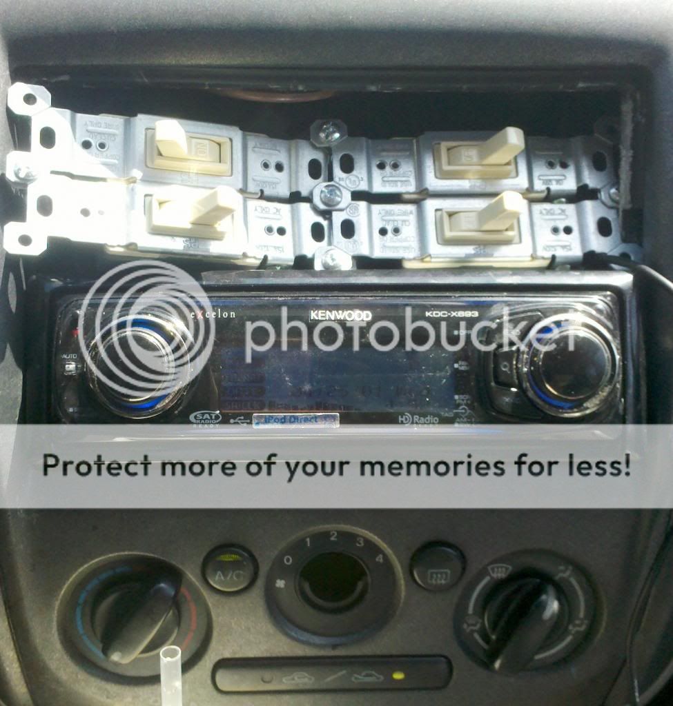
My AC light started to flicker last summer for the first time. I took apart my switch, cleaned and sanded the contacts and all the pins and connectors on the connector plug. That fixed everything and I got to it before the big meltdown. I kinda like the fact that the light flickers at 1.1 volts because it gives me enough warning to clean the switch and contacts again before everything liquefies.
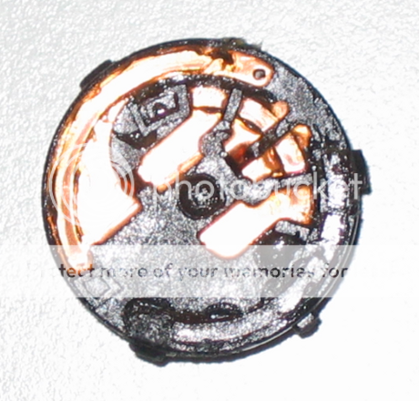
I also noticed that the connector plate inside the switch is kinda spring loaded so I stretched the springs a bit and bent things a bit to help provide more pressure on the contact. I also put a bit of white grease in it.
Let me know if my math is right ,... I know that not all the resistance is in the switch, some is at other connections and some in the wire itself.
I see what you're saying, the flickering A/C light represents a more serious problem. I'd argue that for most people this isn't dangerous, of course if you notice that your switch connector is a bit melty then you should probably address that problem first. We're not trying to bypass an intentional safety system here, we're trying to fix some sloppy engineering.
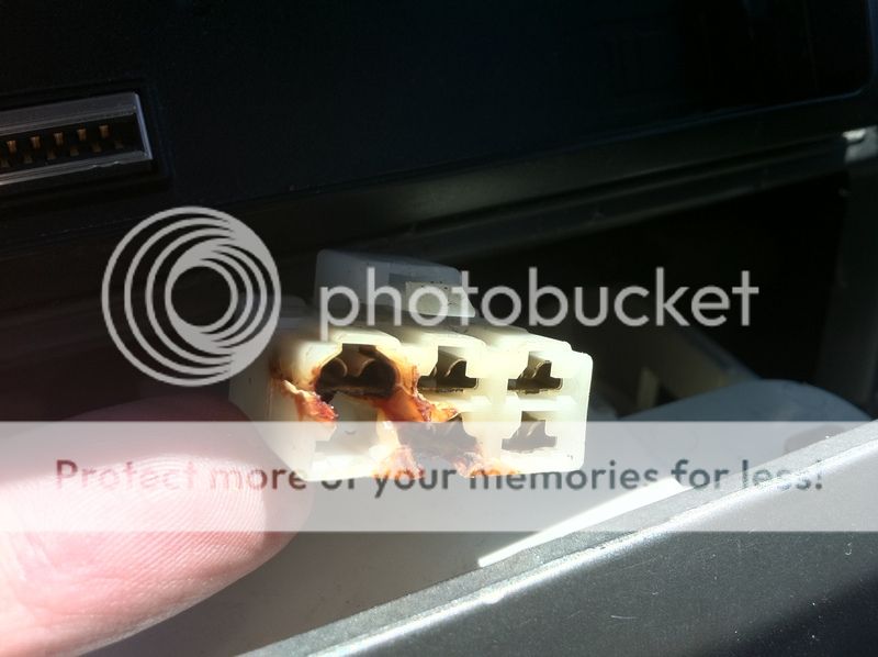
I don't believe the internal resistance of the switch has much to do with this problem. The resistance comes from corrosion on the connector contacts. Keep in mind that in order to get a 1.1V @ 8.8 amps, all you need is 0.125 Ohms of resistance. That's pretty easy to achieve if you assume that both ends of the ground wire have some corrosion and that you'll have ~25 mOhms across the switch. Your pictures would suggest the same thing, the inside of the switch still looks pretty good but the connector contacts are completely tarnished. Thus all of the power that is being dissipated will be along the ground wire, with the bulk of it being dissipated at the two ends of the wire. It would be interesting to throw one of those fancy bonding testers on the ground terminal to see just how bad it really is...