Solution To Flickering Fan Speed 2 Or 3 A/C PART 2

For those who think this is a circuit board issue, why does the problem come and go? I started having issues with speed 2 about 1-1.5 years ago. Sometimes it would work, other times it didn't. About 6 mths ago it stopped working completely. Now speed 3 is doing the same thing, works sometimes, other times nada. Sometimes if I wiggle the control knob, it starts working. This seems like a connection issue more than a circuit board issue. Bad solder joints, bad contacts, etc.

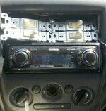
So, I want to try the solder fix. I'm confused about how to pull the A/C knob panel out. I was able to get the dash panel off but I couldn't figure out how to disconnect the a/c knob panel. I cannot fit my hand behind the dashboard. Anyone have a step by step guide with pictures?

Thanks.
 
Pasedena, why couldn't we just put a relay on the A/C compressor itself. It definitely sounds like the current from the A/C clutch is causing the voltage drop across our spotty A/C control unit connections.

That isn't it. The control unit has only little tiny wires, there is no significant current going through it. The problem is that the sensor line on the control unit is attached to line 1 on the fan speed control. The control unit uses that line to see if the blower is on. If it is that voltage is around 1 volt, and if not it floats up to around 12V. The problem is, that on positions 2 and 3 the voltage is just a hair too high for the cutoff on the control board. A circuit like that needs half a volt or more of margin between where it normally sits and where the trigger point is, and here it is like 0.05 volts. Which answers mnkyboy's question - it comes and goes because the signal and trigger levels are so close that ambient temperature and who knows what other factors can push it over the edge.

As I have said before, a simple fix, but a poor one, would be to run a wire from fan line 1, through a switch, through a forward biased diode, to ground. (The diode isn't strictly needed, but they seem to have added one to the existing wiring, although it isn't documented and a I don't know where it is physically located, but I suspect they had a good reason for putting it there.) If that was on it would drag the sensor line down below the trigger voltage on all 4 positions and the compressor would run. The reason it is a bad fix is that the fan would always be on when the switch is closed, and also when the fan switch is off, and the switch is closed, a lot of current (an amp or more) will be going through that new wire. So that needs to be a pretty hefty power diode, and it will get hot. (There are diodes with little metal tabs designed to be bolted to a metal case for this sort of application.) Also the connection to fan switch line 1 needs to be good electrically. The last thing you want is for a crimped connection to fail with 1 amp running through it.
 
Ok looks like I'll be following your instructions on the other thread. Thanks for going through the trouble of writing that up.
 
you would think a Mazda tech that's on this website would tell us what the real problem is and what the real fix is, and I'm sure there's at least one on this forum that is still active, but who??
 
thank good i found this ad mine started a few months ago could only start using 1 and 4 and the slowly move it to 2. i was thinking about buying this new but thats for the advise...:)
 
Cleaned the contacts on my AC fan switch and got it all back -- this is clearly part of the issue. Use a piece of #120 sandpaper doubled over to rough up the inside of the female spade connectors. An emery board works great on the male side in the switch. I pulled apart the switch and sanded those connectors as shown in this thread, but I doubt strongly that this was the problem.

From the other posters here it seems certain that this will only stave off the inevitable. I think the redesigned circuit is in my future. It's impossible that this is only a connector issue, otherwise why does *everybody* see problems on 2 and 3 only? I really appreciate everybody's effort to understand and eventually fix this problem. There's something really awesome about it I can't quite put my finger on.

Cheers,

Jon
 
I finally fixed my blinking A/C problem for good. It's ghetto looking, but it works on all 4 fan speeds. I wired four normal house light switches into the fan control harness.
______
|G|1|2|
|*|4|3|

I attached a wire to connector G (about a foot long) and ran it to 1 post on each light switch in series (the wire runs from switch 1 to 2 to 3 to 4 where it then doesn't run to anything else) . Next i ran a wire(about 6 inches each) from connectors 1-4 to each light switch 1-4 one wire for each switch(attached to the second post on each light switch).

When i flip the switch attached to G and 1, i get A/C and fan speed 1.
When i flip the switch attached to G and 2, i only get fan speed 2, with no A/C... However, i when i flip G to 1 and G to 2 on i get fan speed 2 with A/C.
When i flip switches g1 and g3 i get fan speed 3 with A/C.
when i flip swiches g1 and g4 i get fan speed 4 with A/C.

Here's the picture of my ghetto rig. I'll probably put something better looking in at some point, but this has sovled the A/C problems i've had for almost 4 years. (blinking light, compressor not staying on, etc.)
 

Attachments

  • AC fix.jpg
    AC fix.jpg
    334.2 KB · Views: 553
Props for the creativity, but that picture belongs on "there I fixed it"

I have already submitted it to them. However, 100+ degree heat(with A/C only working on fan speed 1) makes me do crazy things.

Maybe i can get an award for cheapest fix? $.79 for each light switch plus the cost a yard of wire. i think i came in under $5. My wife was yelling at me as i assembled everying at the dining room table. ("you're gonna kill yourself and set your car on fire!!!!")
 
Last edited:
That isn't it. The control unit has only little tiny wires, there is no significant current going through it. The problem is that the sensor line on the control unit is attached to line 1 on the fan speed control. The control unit uses that line to see if the blower is on. If it is that voltage is around 1 volt, and if not it floats up to around 12V. The problem is, that on positions 2 and 3 the voltage is just a hair too high for the cutoff on the control board. A circuit like that needs half a volt or more of margin between where it normally sits and where the trigger point is, and here it is like 0.05 volts. Which answers mnkyboy's question - it comes and goes because the signal and trigger levels are so close that ambient temperature and who knows what other factors can push it over the edge.

As I have said before, a simple fix, but a poor one, would be to run a wire from fan line 1, through a switch, through a forward biased diode, to ground. (The diode isn't strictly needed, but they seem to have added one to the existing wiring, although it isn't documented and a I don't know where it is physically located, but I suspect they had a good reason for putting it there.) If that was on it would drag the sensor line down below the trigger voltage on all 4 positions and the compressor would run. The reason it is a bad fix is that the fan would always be on when the switch is closed, and also when the fan switch is off, and the switch is closed, a lot of current (an amp or more) will be going through that new wire. So that needs to be a pretty hefty power diode, and it will get hot. (There are diodes with little metal tabs designed to be bolted to a metal case for this sort of application.) Also the connection to fan switch line 1 needs to be good electrically. The last thing you want is for a crimped connection to fail with 1 amp running through it.

Well, you are correct sir. I just installed a manual switch on each fan speed that can be turned on and off. If the swich for fan speed 1 is on, all other fan speeds work with AC.
 
I attached a wire to connector G (about a foot long) and ran it to 1 post on each light switch in series (the wire runs from switch 1 to 2 to 3 to 4 where it then doesn't run to anything else) . Next i ran a wire(about 6 inches each) from connectors 1-4 to each light switch 1-4 one wire for each switch(attached to the second post on each light switch).

Uh, "1 post"? That light switch has two connectors, and the ground one is almost certainly electrically connected to the exposed metal parts of the switch visible in the picture. Wire those switches blower side to ground post and it would still switch the same, but it might get pretty exciting if a ground ever got near that metal. I don't think you did that because it would probably have already arced if it was wired that way. Just to be clear, if this is wired backwards there would be an exposed contact at 12V that could easily source 10A if shorted to ground.
|

Each light switch has two "posts" that are attached to a plastic box behind what you can see in the picture. they screw down into a plastic housing. When you put a switch into the ON position it just connects the first "post" to the second "post". I ran an insulated wire to the first "post" on each switch from G on the fan swich wiring. (post #1 on each switch can connect the wire that is connected to post #2 to G, in the same way the fan speed selector switch can) The wire is cut in such a way that the only exposed wiring is secured under the screw down "post". The metal you see in my picture does not actually touch any of the wiring, it's simply there to secure the light switches to the wall if they were to be used as intened.


EDIT: i re-read your post, the metal surrounding the switches is not connected to either "post" on the back of the switch, i tested with a multi-meter first.
 

Attachments

  • ac switch.jpg
    ac switch.jpg
    14 KB · Views: 591
Last edited:
i re-read your post, the metal surrounding the switches is not connected to either "post" on the back of the switch, i tested with a multi-meter first.

Right, what I said wasn't quite right either. Current wiring codes have the exposed metal grounded. That grounding might be indirect - if the switch is wired into a metal box and that box is grounded, then the metal switch surfaces will also be grounded. The neutral and ground go back to the same point, so when measured at the switch plate/pole they appear to be shorted. This is a safety measure in case the switch fails and shorts one pole to the exposed metal (which comes out of the light switch plate on the two exposed screws). If the neutral shorts you probably couldn't tell. However, if the hot wire shorts and the switch is properly grounded it will blow the fuse, which is the desired failure mode. Much better than touching the mounting screw and the sink handle and dropping dead!

The same safety consideration applies here. Perhaps more so, since who knows what kind of shape those switches are going to be in after an accident or a spilled coke. If the hot side shorted to the metal and from there to ground the fan would start blowing. (It will not open the blower fuse as that is rated for a dead short from one side of the blower to ground == fan speed 4.) If that short happened and that metal was not grounded then it would be a shock hazard. Measure the resistance between the exposed metal on the switches and some bare metal on the chassis. If it is very low then you have effectively grounded these plates through the mounting screws. (We can't tell what it is screwed into, could be plastic, in which case those surfaces are not grounded.) If there is a large resistance then run a ground wire.
 
Last edited:
I attached a wire to connector G (about a foot long) and ran it to 1 post on each light switch in series (the wire runs from switch 1 to 2 to 3 to 4 where it then doesn't run to anything else) . Next i ran a wire(about 6 inches each) from connectors 1-4 to each light switch 1-4 one wire for each switch(attached to the second post on each light switch).

Which wire did you use? Gauge and temperature rating. The goal is to have the voltage drop through the wire <3%, preferably much less than 3%. The ground and fan speed 4 wires need to able to handle 10A continuously. The other fan speed wires handle less current because of the blower resistor.
 
Which wire did you use? Gauge and temperature rating. The goal is to have the voltage drop through the wire <3%, preferably much less than 3%. The ground and fan speed 4 wires need to able to handle 10A continuously. The other fan speed wires handle less current because of the blower resistor.

I re-used a 16 gauge 13 amp outdoor extension cord, cut to the legnths i needed. I'm not sure what the temp rating is, but i figured if it was made for outdoor weather, bit would be better.
 
I re-used a 16 gauge 13 amp outdoor extension cord, cut to the legnths i needed. I'm not sure what the temp rating is, but i figured if it was made for outdoor weather, bit would be better.

If you run fan speed 4 for a while does that wire or the ground wire become warm to the touch? If it does you might want to go to 14 gauge. (Unless it starts to fray the wire you used should theoretically have enough capacity.)

Wire rated for car use will withstand much higher temperatures than outdoor extension cord wire. Insulator ratings of 80C or 105C are common.
 
Ok, I've just spent the entire morning reading several hundred posts on this issue dating all the way back to 2004...and it seems there are kind of two seperate issues that were being discussed on what is causing this, and how to fix it...I don't really have anything to add other than some carefully detailed information on my blinking problems with a 2002 Protege5 with roughly 140k miles...

as of now I have not attempted anything on fixing it, and may try to get through the end of this summer before I do...

I bought my car new in Feb 2002 and noticed the blinking AC light the very first summer (as well as noticing that these cars do not have a very powerful AC altogether)...Up until this summer (i'll get into that in a bit) I ONLY had the problem at speed 2, and it would blink occasionally, but never to a degree where it really bothered me...

Over Memorial day of 2011 I removed the entire front face plate as I was painting all the trim pieces...this was the first and ONLY time so far in the 9'ish years of owning this car that it was ever removed for any reason...This has also been one of the hottest summers so far that i can remember in central PA...

for most of the summer I hadn't noticed anything...but in the past few weeks its been over 100 degree several times, and I can't really park out of the sun where I work...getting in the car at 4 pm after a full day of sun is ridiculous even with windows cracked (but usually can't do that because afternoon thunderstorms have been just as regular as the heat)...

what i've noticed is that when the car is torched inside...and the 20 minutes of driving or so before it is truly cooled to 'room temperature', fan speed 2 is now worthless...it will blink about twice a second non stop, you could almost set a watch by it...fan speed 3 now blinks occasionally, maybe 15-20 times a minute, 1 and 4 are solid green...

what I have definitely confirmed though is that this ONLY happens when the car is still ridiculously hot inside...after it is cooled noticeably, fan speed 3 doesn't blink at all, and 2 goes back to the way it was for the past 8 years...1 and 4 work like always...

I understand that this is a circuit issue too, but based on what i've noticed it definitely has something to do with contacts and their expansion properties when heated as well...interior temp is affecting mine, and my problem DEFINITELY got worse and much more noticeable ever since i disconnected this now infamous fan speed/AC switch harness...which has to be why many have crimped or soldered the leads and had much better performance...

My guess so far is that the more you disconnect that harness for whatever reason, the more noticeable the problem will become...I've yet to read about one person having the no AC on 2 and 3, blinking on 4, etc and never having disconnected that harness...

Again, i know this isn't news, but anyone coming into this thread this late might be able to add to when and why their problem got worse which can help further narrow it down...is anyone having problems that never disconnected that harness?
 
I have noticed down here in FL that my #2 and #3 settings blink more when the inside of the car is SUPER hot. Once the car has cooled inside, it happens WAY less...if at all.
 
little update:

I just drove about 30 miles today with someone else in the car staring at that AC light the entire time haha...Today was much cooler than yesterday, and cloudy (about 80 degrees)...the car never heated up much while it was parked, maybe 5 degrees or so...but it was ambient just by opening the doors to get in...

the light did NOT blink one time...fan speed set to 2 the entire way...24hours ago speed 2 was non stop blinking when the car was heated up...

I didn't check any other speeds while I was moving, 2 has always been the most problematic...

just as a reference I have front and rear AWR engine mounts installed (the red hard ones), and have for several years...It makes it VERY easy to tell when the compressor kicks on because the engine mounts don't take any of the slack...it was lunging so bad yesterday at low speeds with the setting at 2 that I thought it was misfiring...

I don't know what this narrows it down to problem wise...but I can definitely confirm that it is 100% related to the internal temperature of the car...
 

Latest posts

Back