
I have a:
2016 Mazda CX-5 –A/T, Grand Touring Model, Tech Package, AWD, Navigation (NO iActivesense)
This write-up describes how I installed the JDM Mazda paddle shifters onto this particular USA spec. model. Other models may vary, your experience may vary. This is simply a chronicle of how I completed this task. If you choose to do the same, the responsibility for your actions lie with you alone.
Also, I want to give credit where it’s due. I was only able to do this because of the thread in the “Engine and Transmission” Forum and with the insight, links and photos of members like Svshootingstar, Farenheight and Berner to name a few. Everyone who added to that thread has also helped make this one. Since I was able to do this with the help of others, I figured I’d contribute to the board by putting it all together in one place.
*Virtually all automotive wiring harnesses have some sort of locking mechanism the requires locking/unlocking prior to insertion/removal of wiring. It is solely your responsibility to correctly install any wiring on your own vehicle. If you think otherwise, pay someone to do it for you*
Parts Purchased:
Source: www.oemmazdaparts.com
GJS2-66-3P0B - Paddle Switch (came with its own wiring sub-harness)
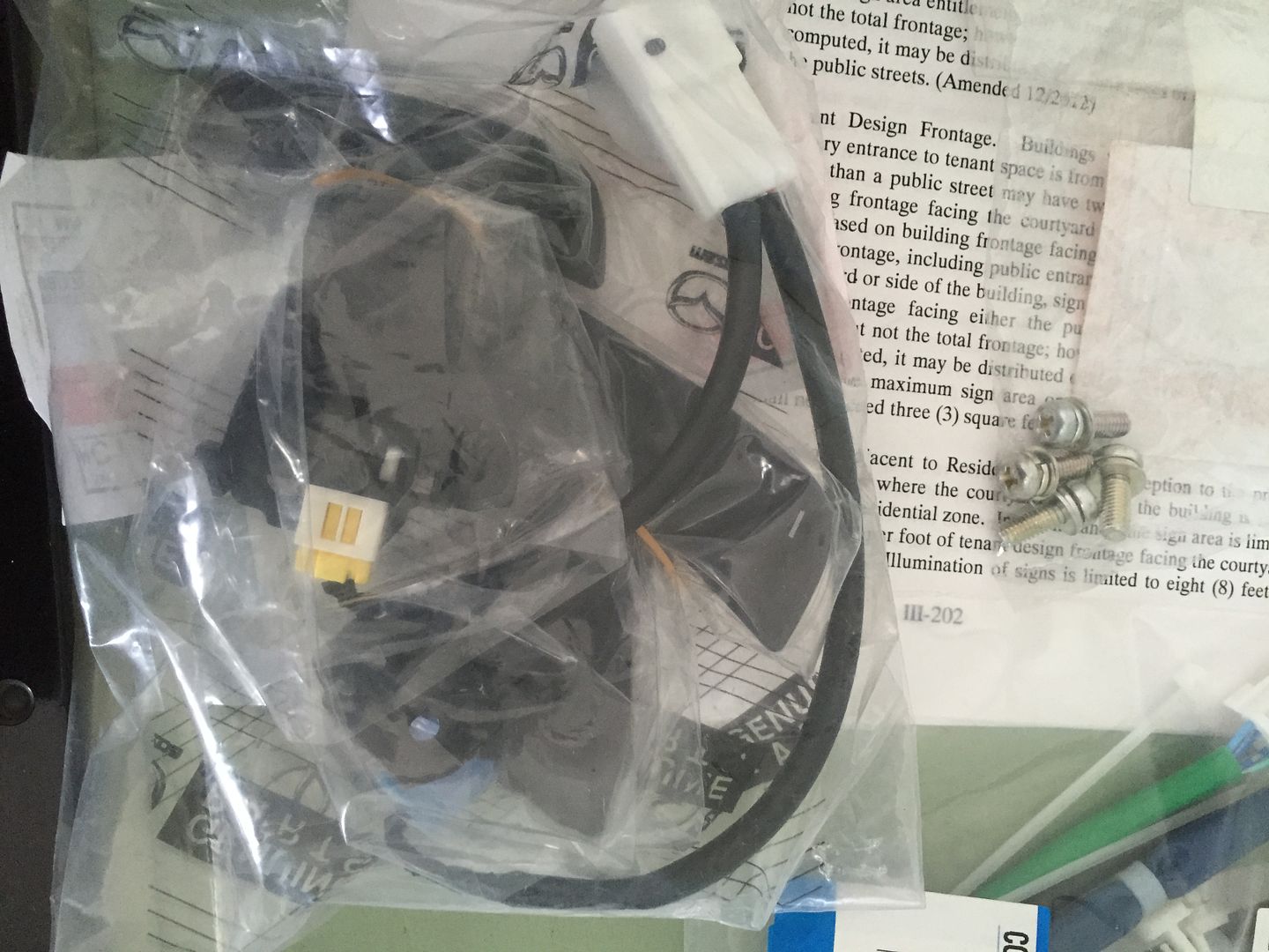
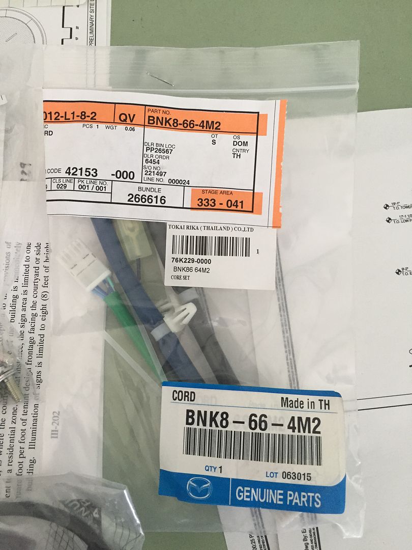
BNK8-66-4M2 - Wire (Connectors for the paddles & OEM steering wheel pods)
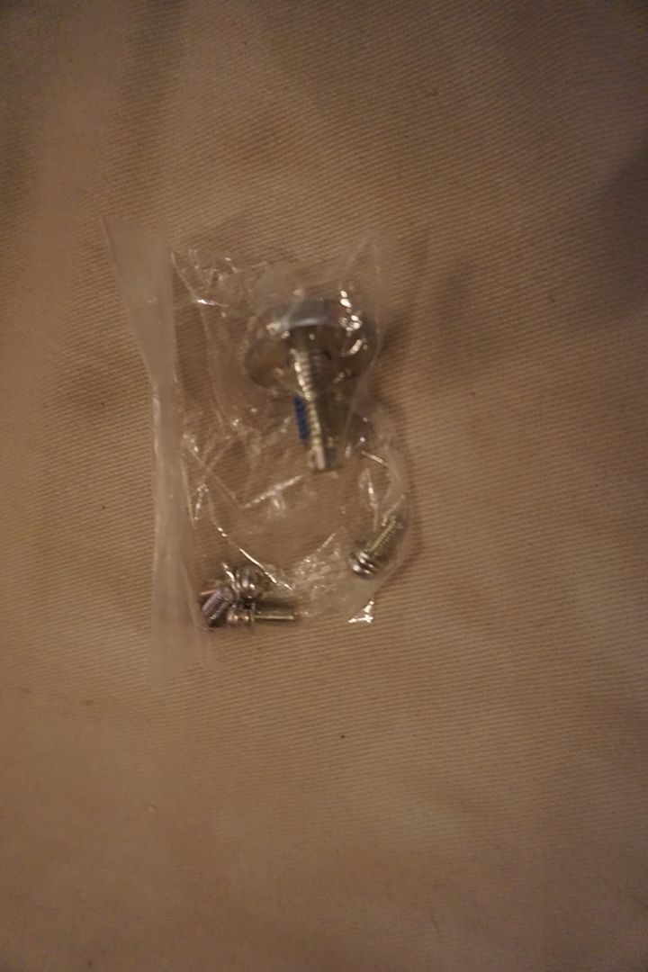
BHN9-32-750 - Parts Set, Steering Wheel (small screws for steering wheel) **If ordering D10J-V7-480 from Japanparts below, this is not needed**
9YA0-11-003A or 007 – Steering Wheel Bolt (Bolt that holds the steering wheel in place) **If ordering D10J-V7-480 from Japanparts below, this is not needed**
www.japanparts.com (Special Order – Not listed on their website)
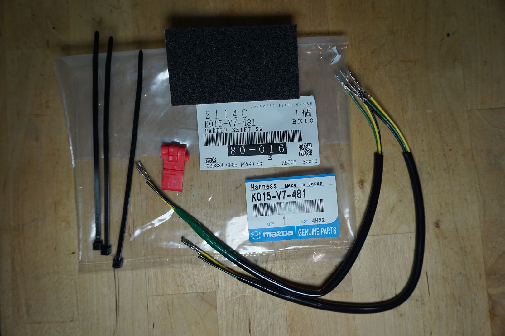
K015-V7-481 Paddle Shift SW Harness (note this item came with two identical harnesses, one end of the harness (vehicle side) is different. On one, the prongs are the short type, and on the other they are the long type. My vehicle used the long version).
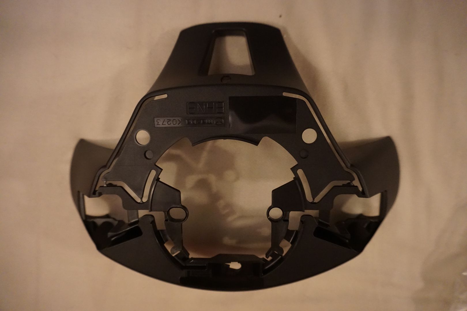
D10J-V7-480 - Rear Cover + Small screws for steering wheel + Steering Wheel Bolt (these parts came as a set under this one part order). This also came with a set of instructions for installation (in Japanese).
Tools Used:
Long Hex (I wrapped this in electrical tape for this project in order to help avoid conducting electricity when working on the airbag).
Phillips screwdriver
Torque wrench
Socket 21mm, 10mm
Dental picks
X-acto knife
Disassembly Steps:
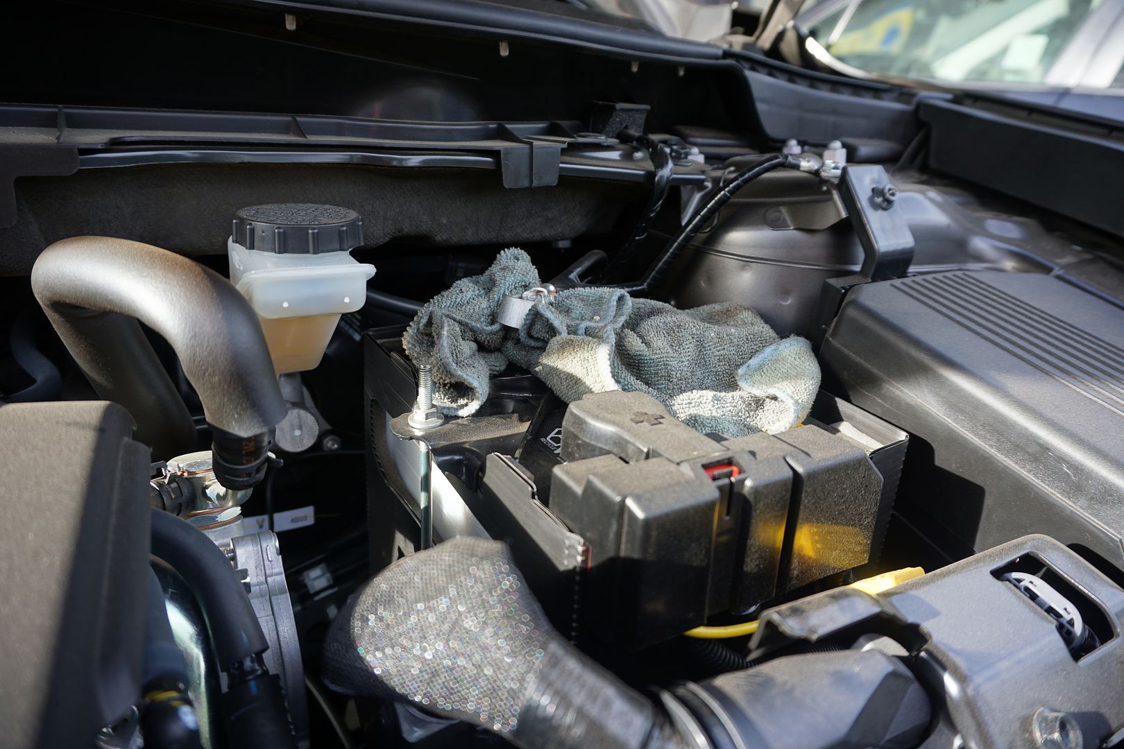
1) Disconnect negative battery terminal
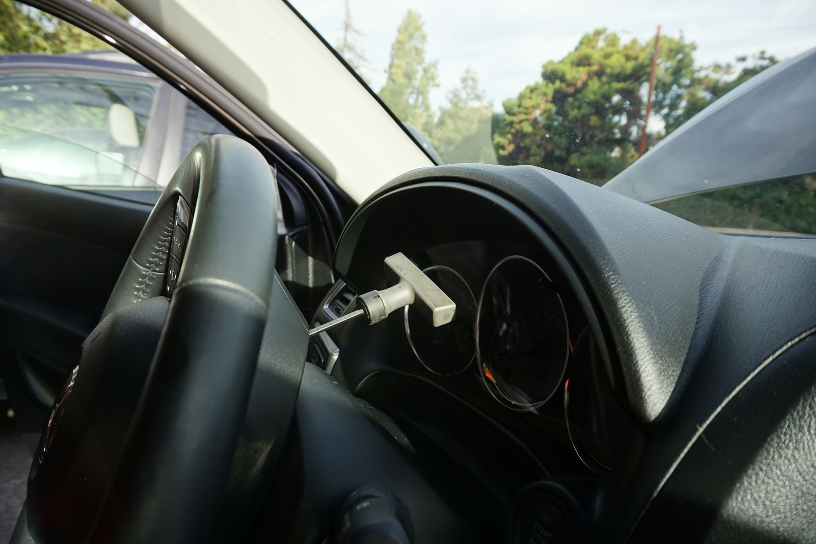
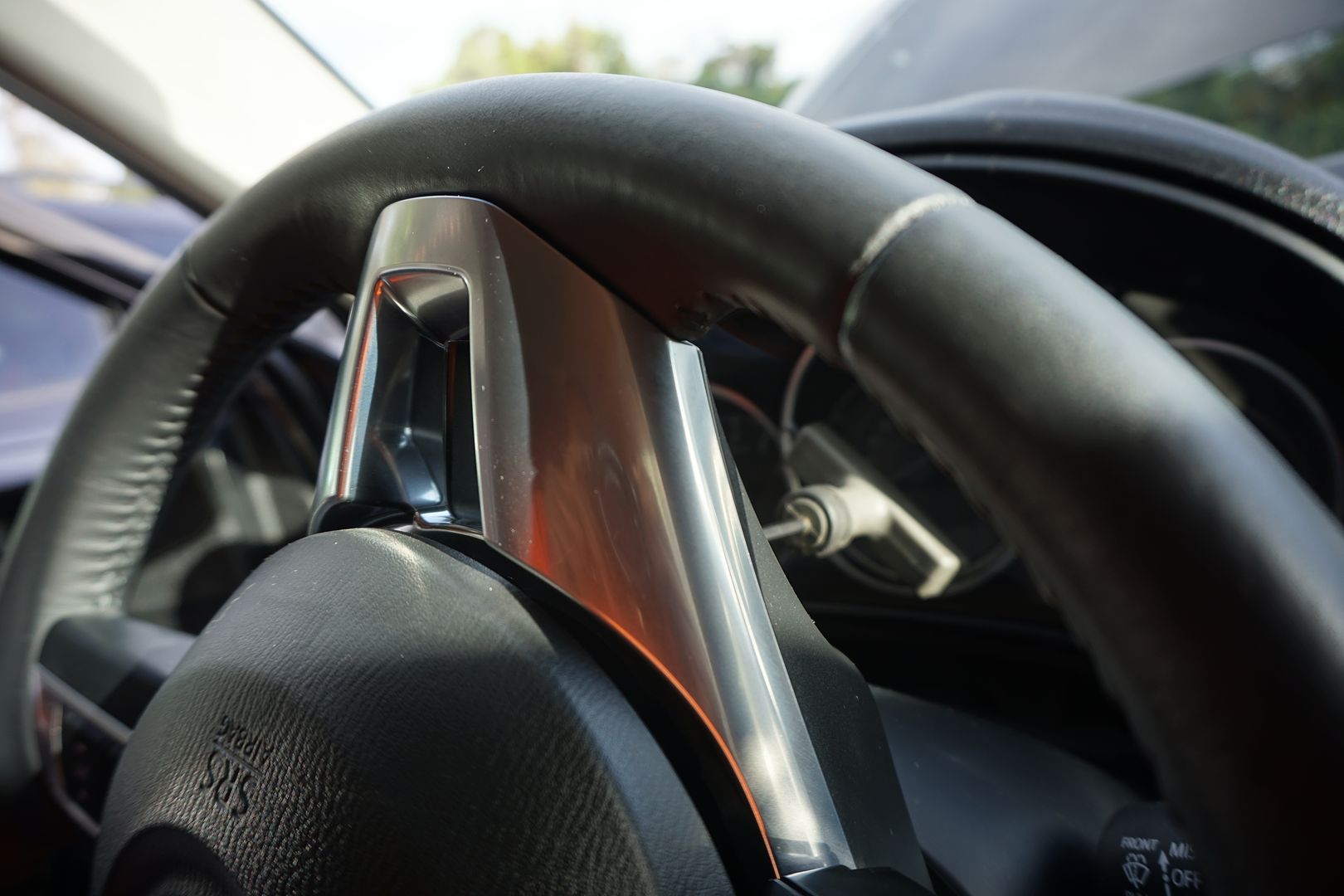
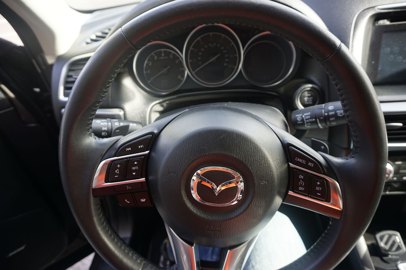
2) To remove the airbag one needs to insert a long thin tool into each of the three service holes in order to unlock it from the steering wheel. I used hex tool wrapped in electrical tape. (Refer to the shop manual). I rotated the steering wheel to access all of the holes, one at a time. You can only access them when they are at the top of the steering column.
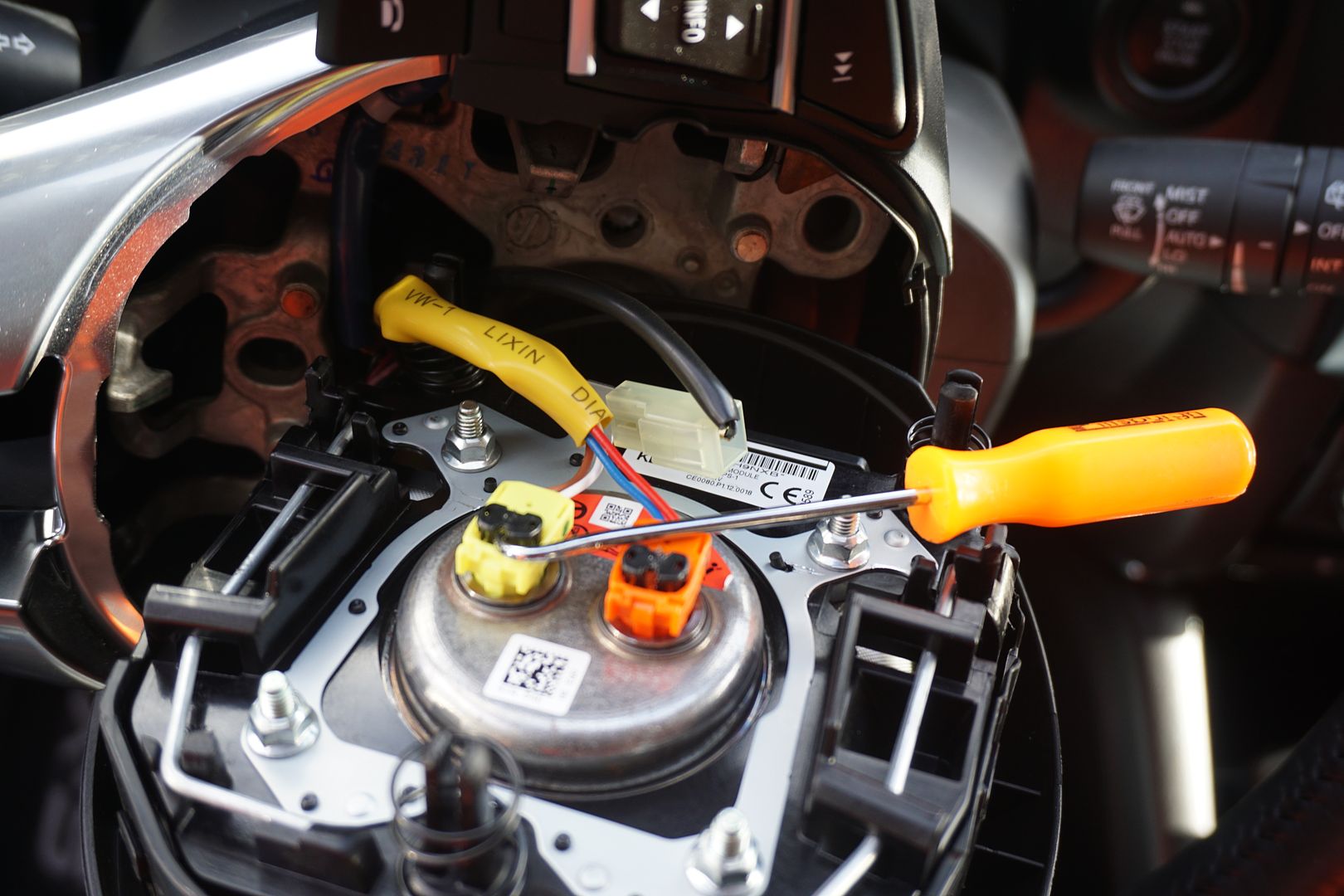
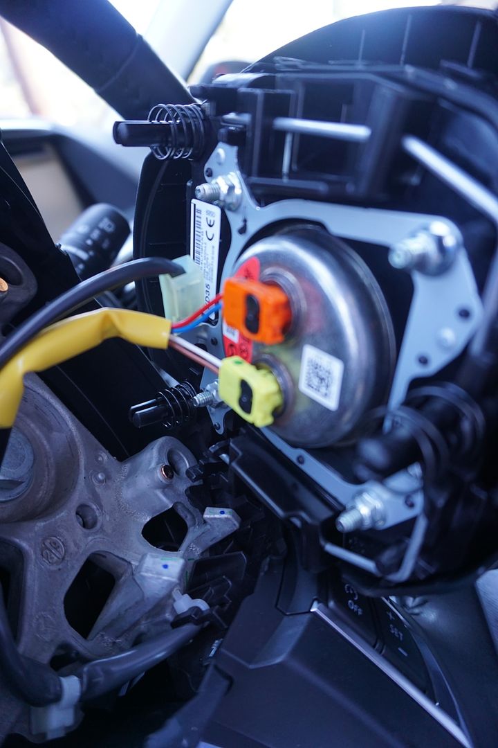
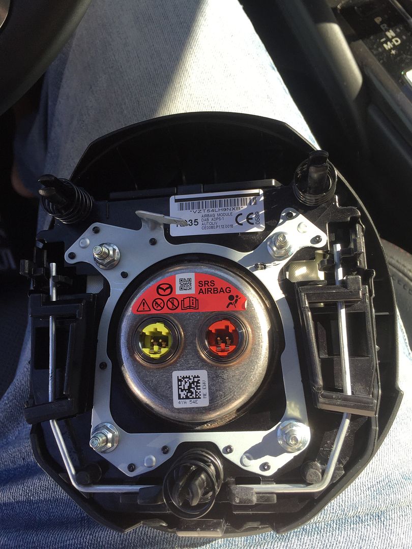
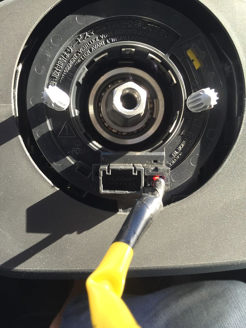
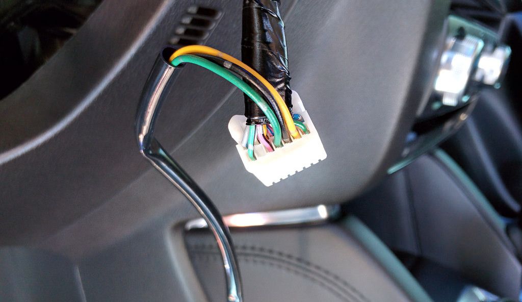
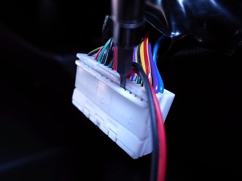
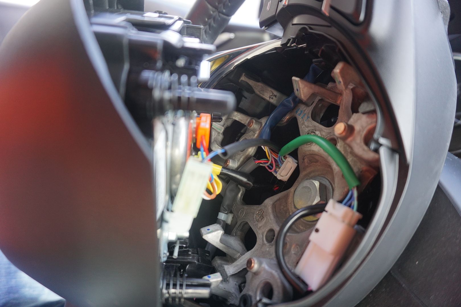
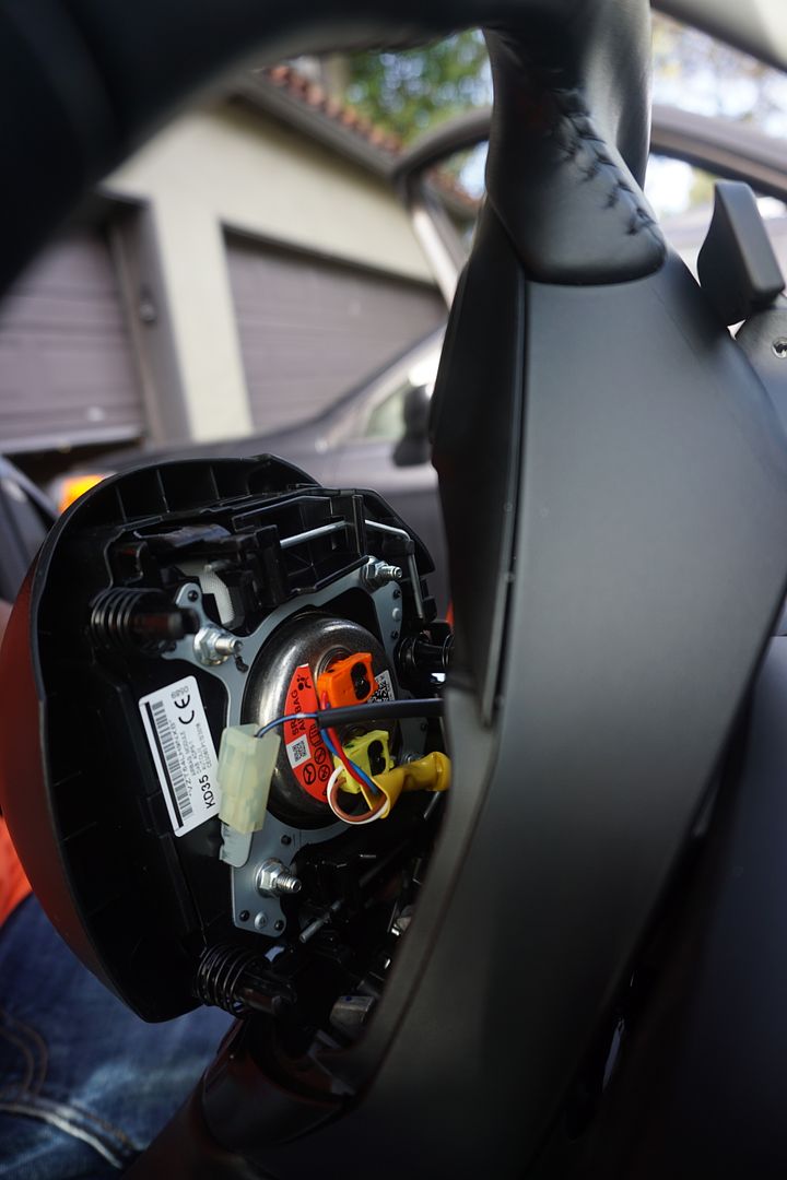
3) Once all three pins have been unlocked, I gently moved the airbag away from the wheel just far enough to gain access to the wires connecting it to the car. Disconnecting these wires from the harness freed the airbag for removal. I used a pick to pull straight up on the black portion of the connector. This can be pulled completely off, but it is not required. Then I grasped the connector with my fingers and pulled it away from the airbag. Of the three photos below, the first photo shows the connectors unlocked and ready to be pulled from the airbag, the second photo shows the connectors locked in place, and the last photo shows the connectors fully removed.
3.1) I used my fingers to remove the horn connector next.
4) Once all connections were removed, I placed the airbag someplace safe to avoid accidental deployment.
5) Use the (21mm) socket and a ratcheting wrench to remove the bolt holding the steering wheel in place.
6) I discarded the bolt, as I’ve read that it is intended as a “one time torque” bolt. It will be replaced later.
7) I made a note of the direction that the steering wheel was facing when I removed the nut to be sure I’d place it back in the exact same orientation.
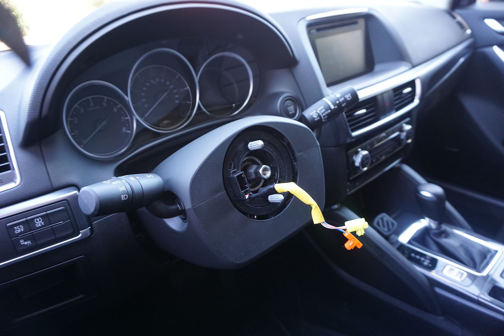
8) I then disconnected the existing wheel side pod harnesses from the main vehicle harness.
9) I removed the steering wheel from the vehicle and placed it on my workbench.
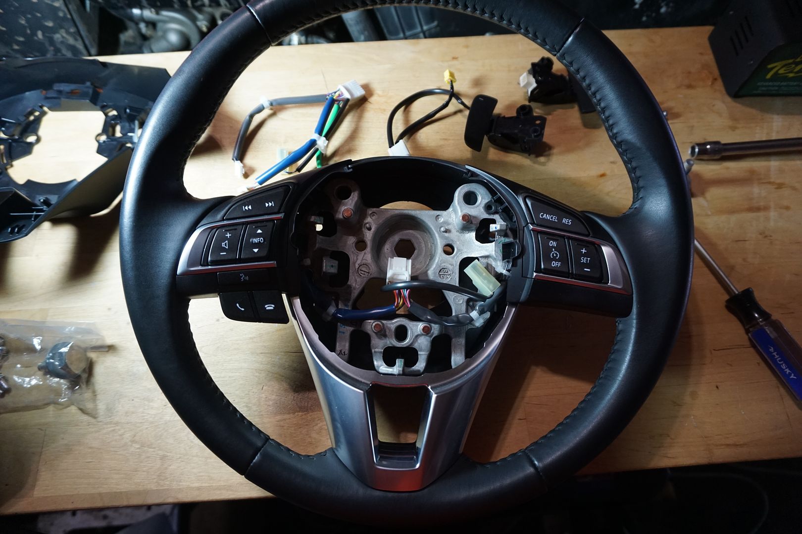
10) I removed the left side pod that holds the hands free & stereo buttons from the wheel. It comes off by sliding the plastic tab to the left and pulling gently/ firmly straight away from the wheel.
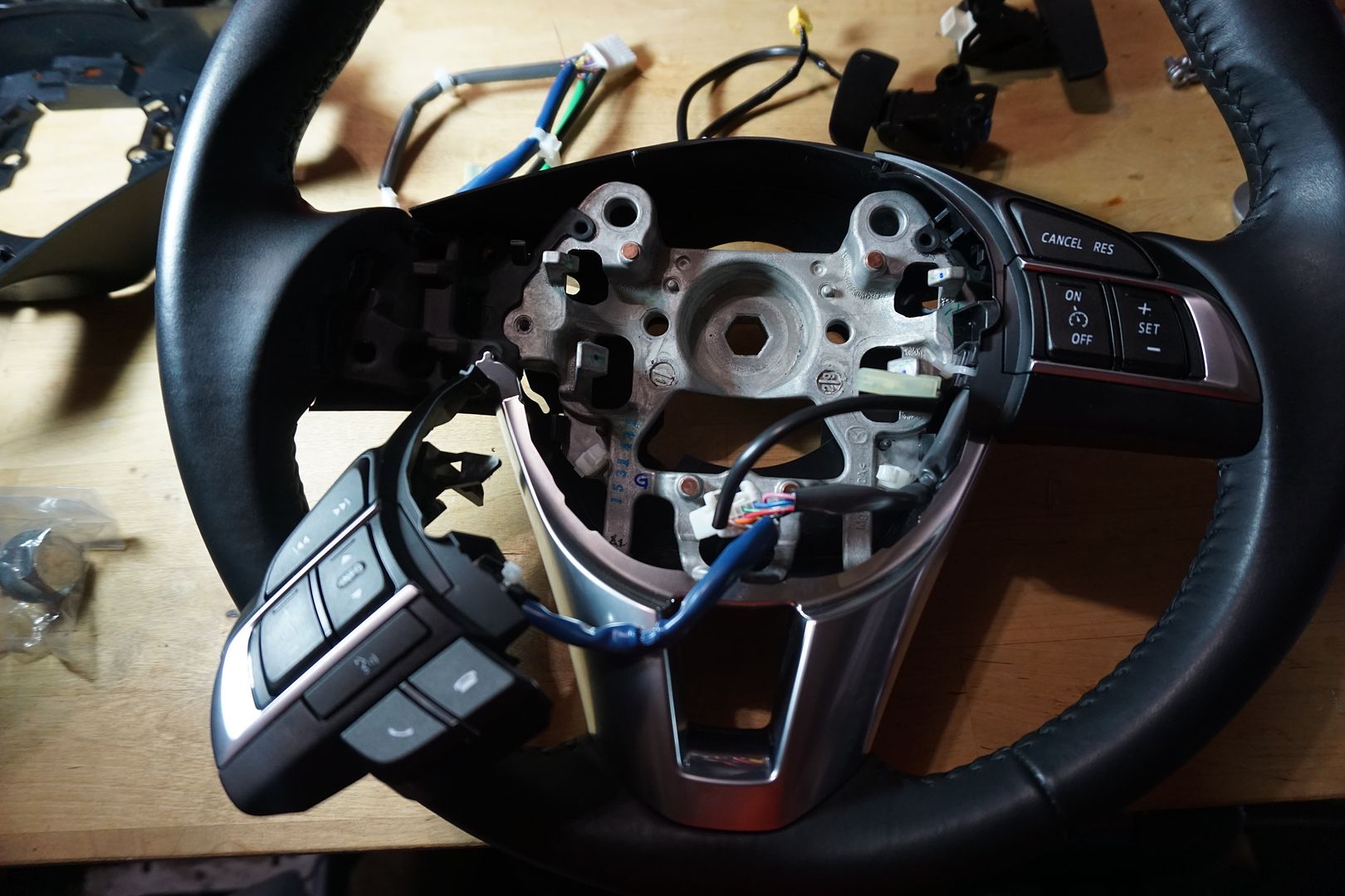
11) Then I removed the right side pod in a similar manner to the left.
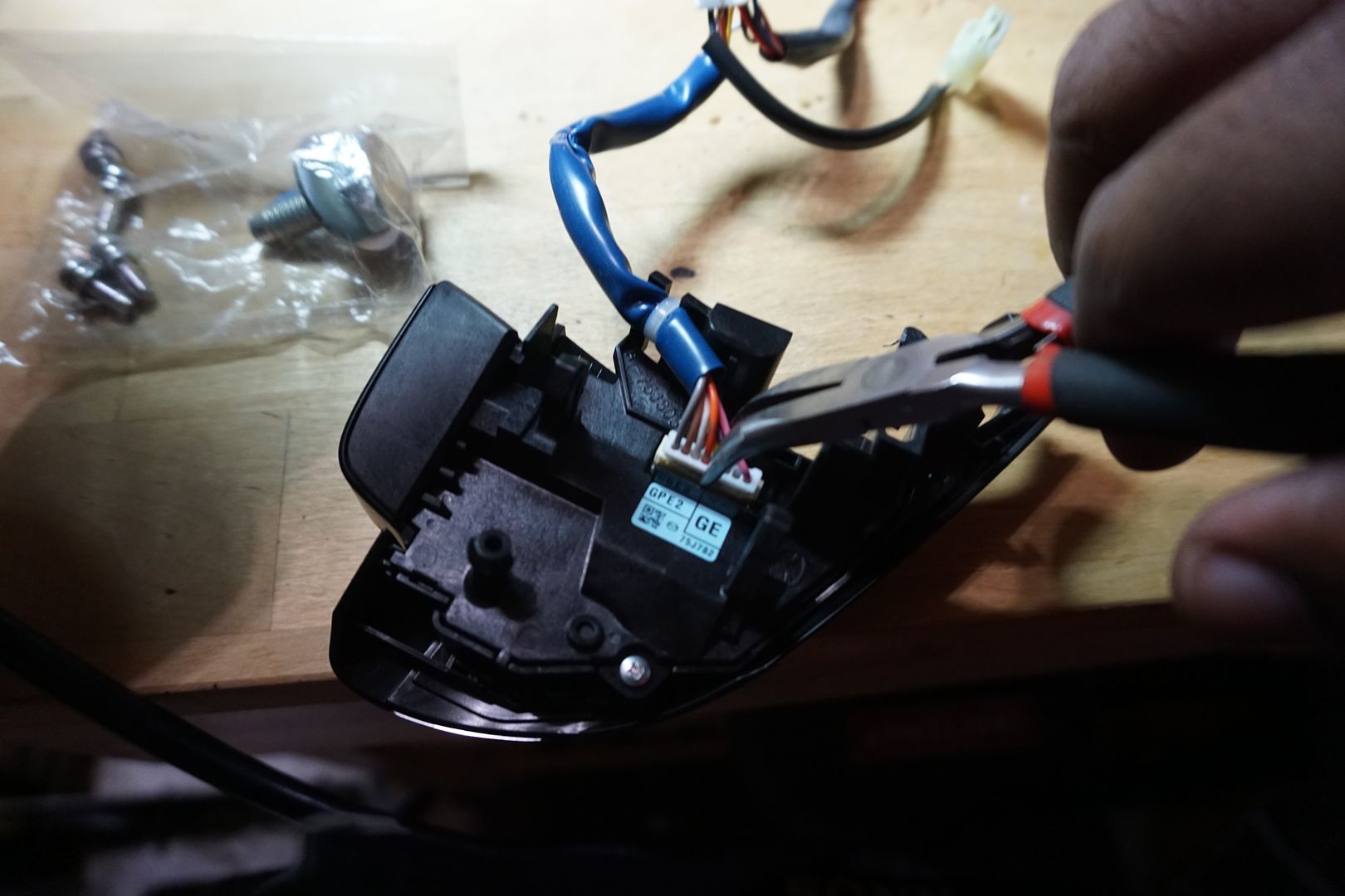
12) Then I removed the wiring from both pods. Be careful to release the locking tab before pulling on the connector.
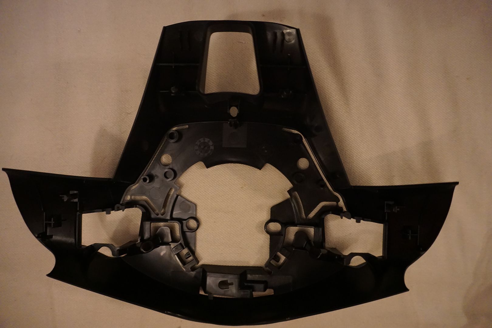
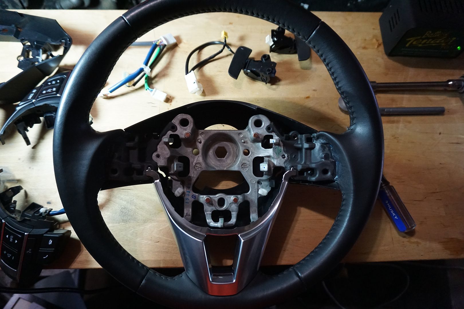
13) Lastly, I removed the rear cover by pulling the plastic tabs away from the main part of the steering wheel and the pulling off the cover.
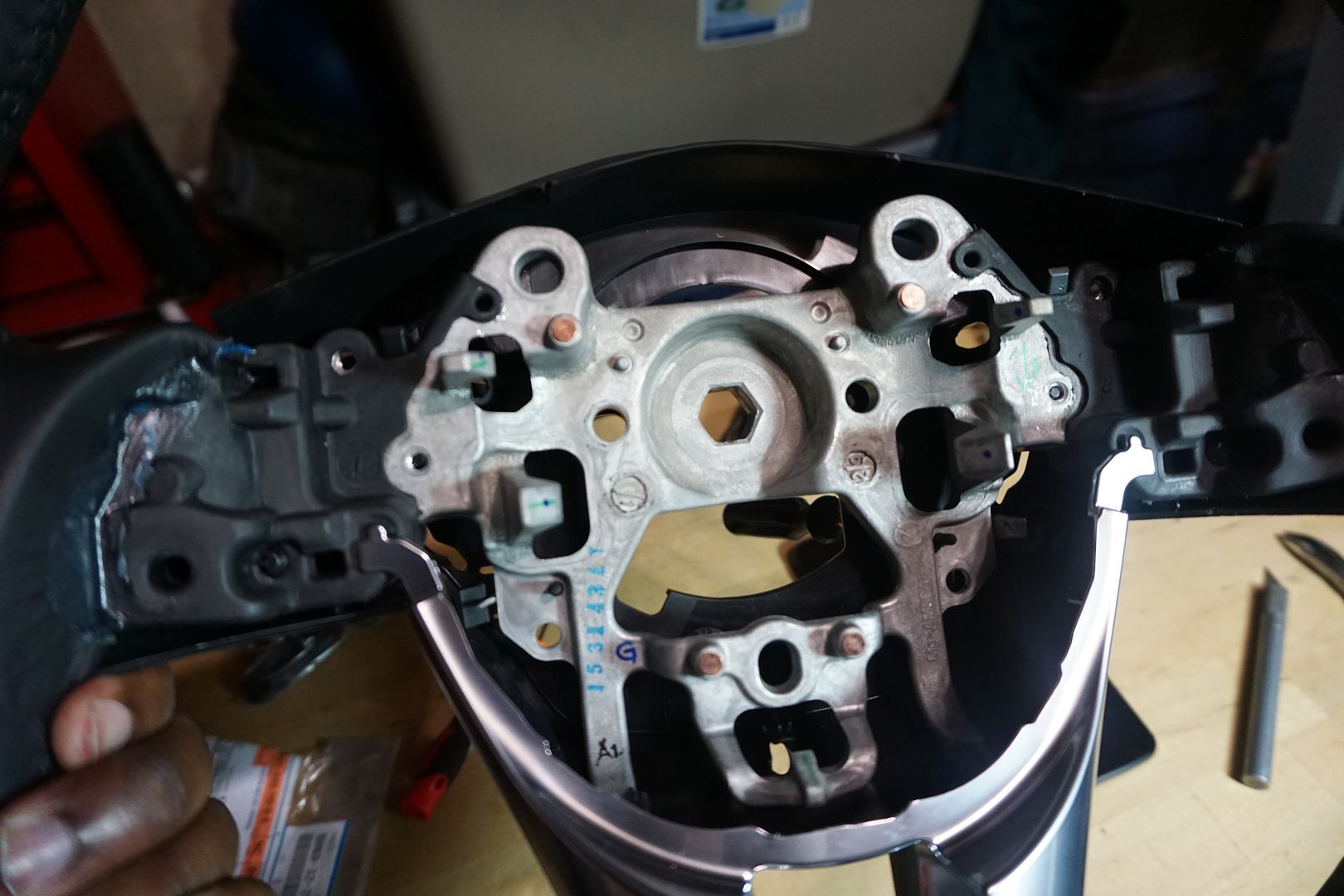
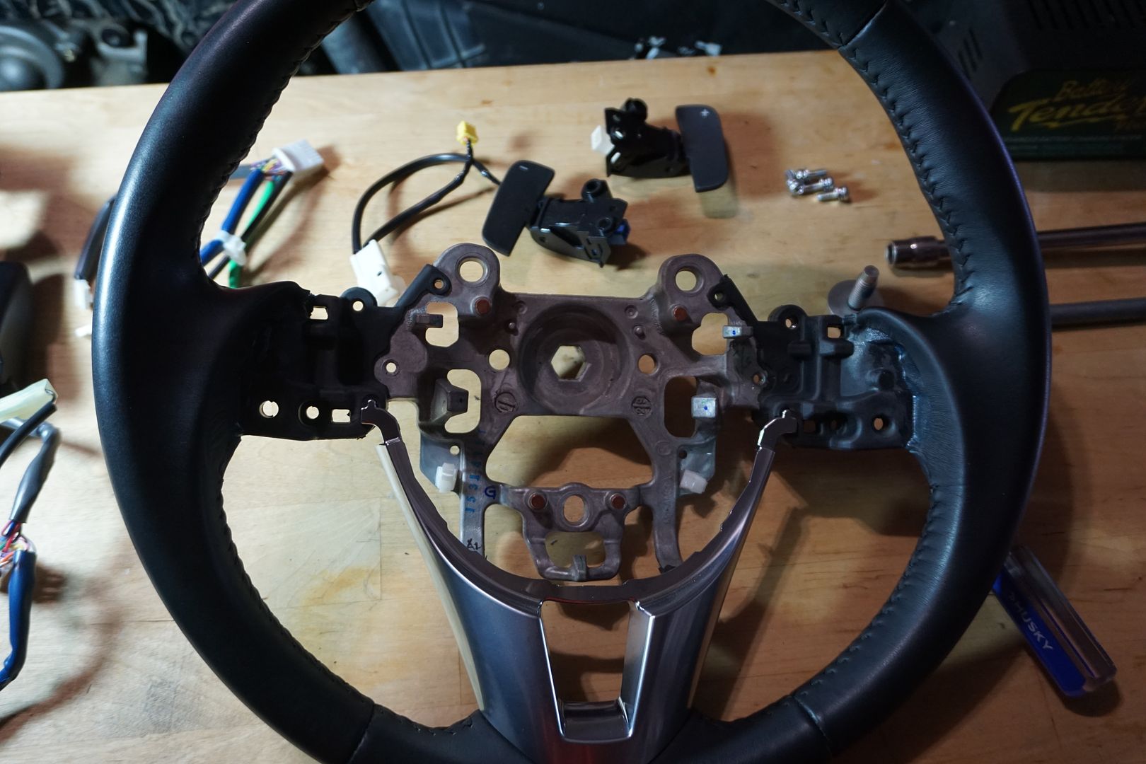
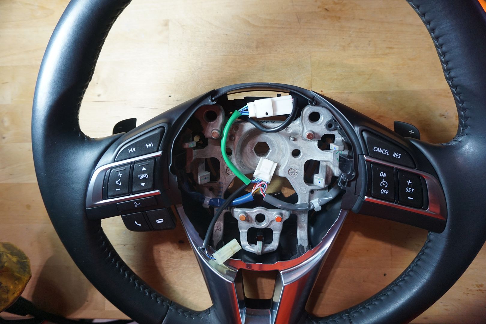
14) This leaves you with the base steering wheel.
Disassembly is now complete. It’s time for re-assembly.
Assembly Steps:
1) I placed the wiring attached to the paddles themselves (GJS2-66-3P0B) into the slots provided on the new rear cover (D10J-V7-480).
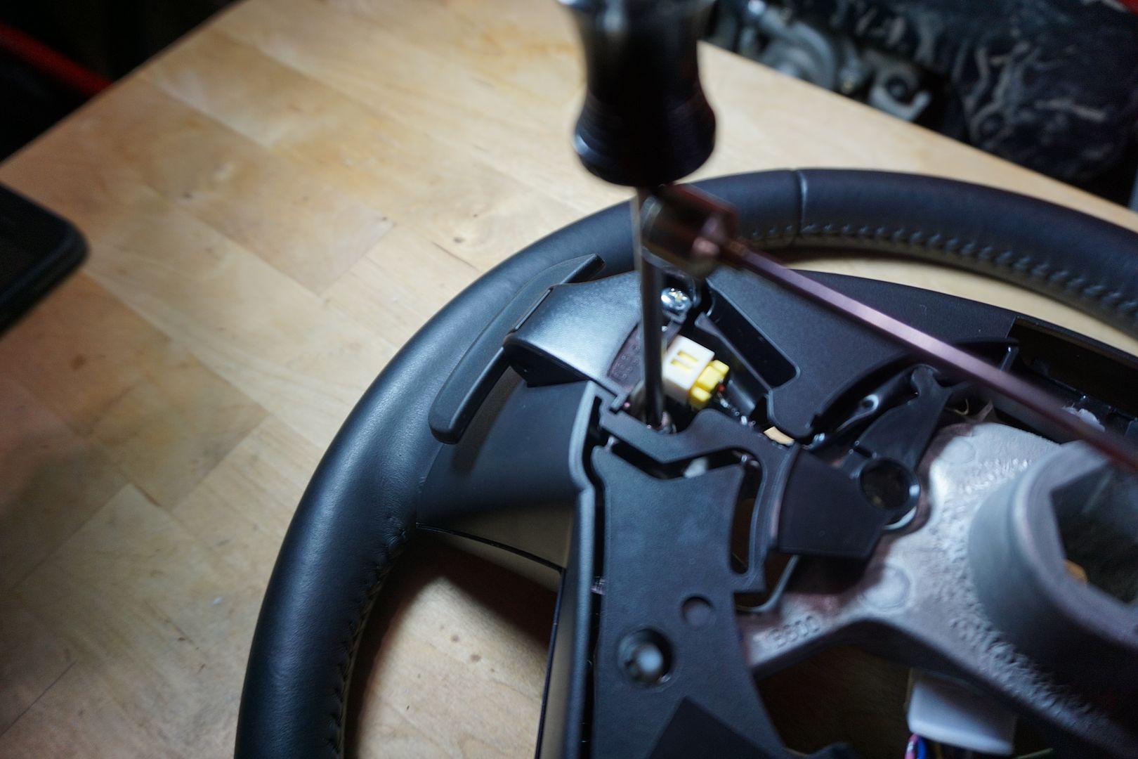
2) I then placed each paddle in its place and secured it with the two screws included in the kit (D10J-V7-480). The steering wheel was already pre-drilled and tapped for these screws.
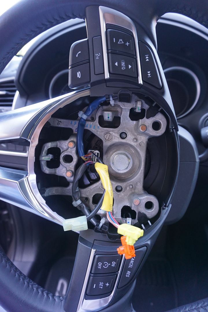
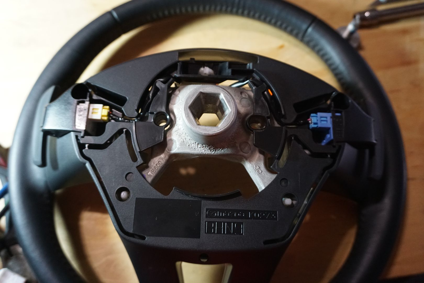
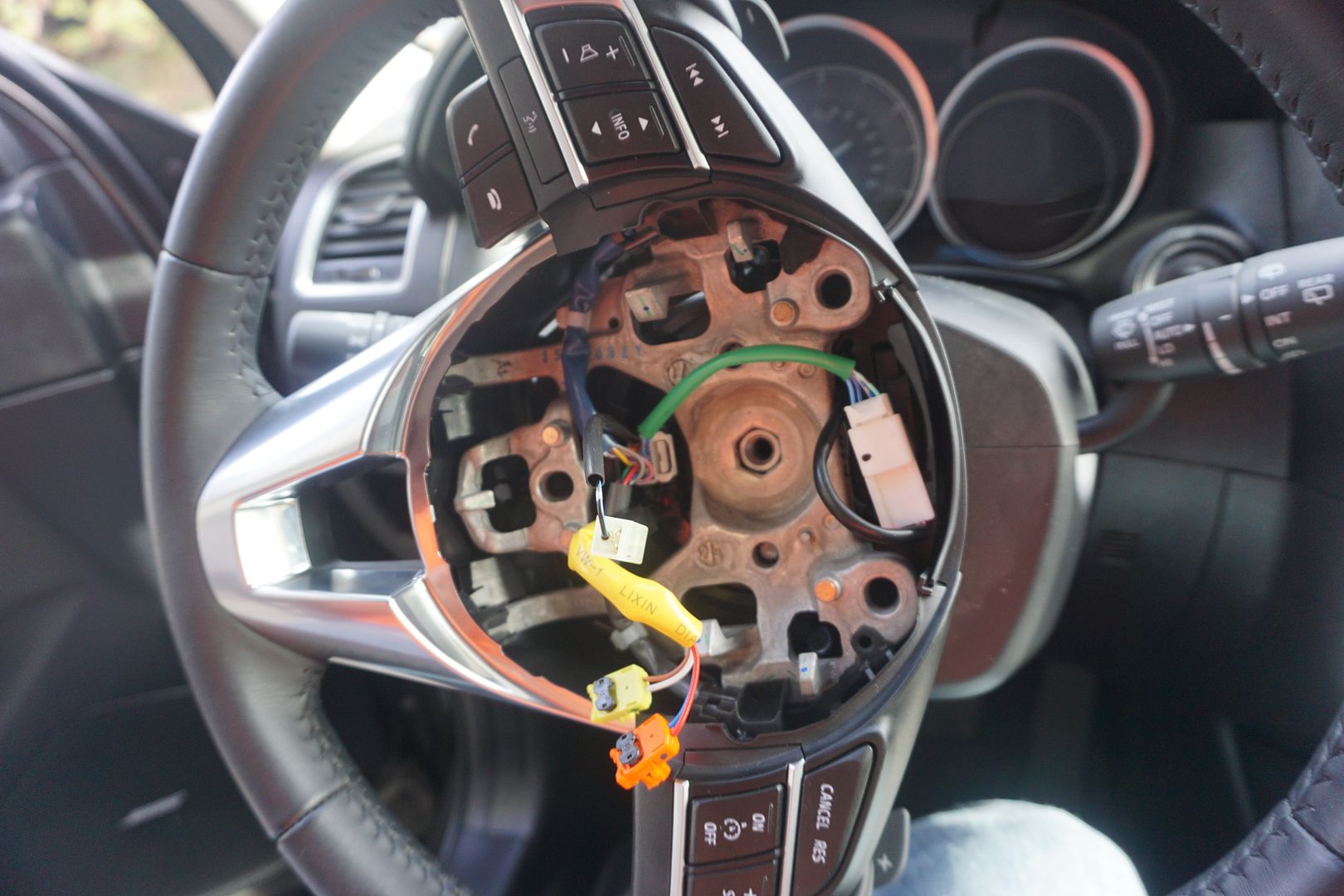
3) Afterwards, I attached the wiring harness (BNK8-66-4M2) to the paddles wiring harness (GJS2-66-3P0B) and routed it inside the steering wheel hub as shown above.
4) Then I re-attached both side pods as indicated and put the wheel aside for the moment.
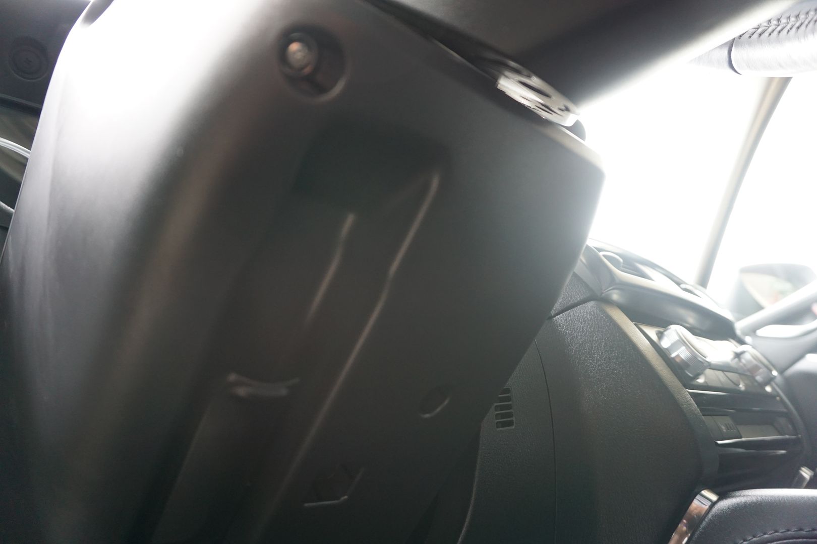
5) Then I went back to the car and removed the two screws holding the bottom portion of the steering column cover in place.
6) I slightly pushed forward and up on the top portion of the steering column cover to open it up.
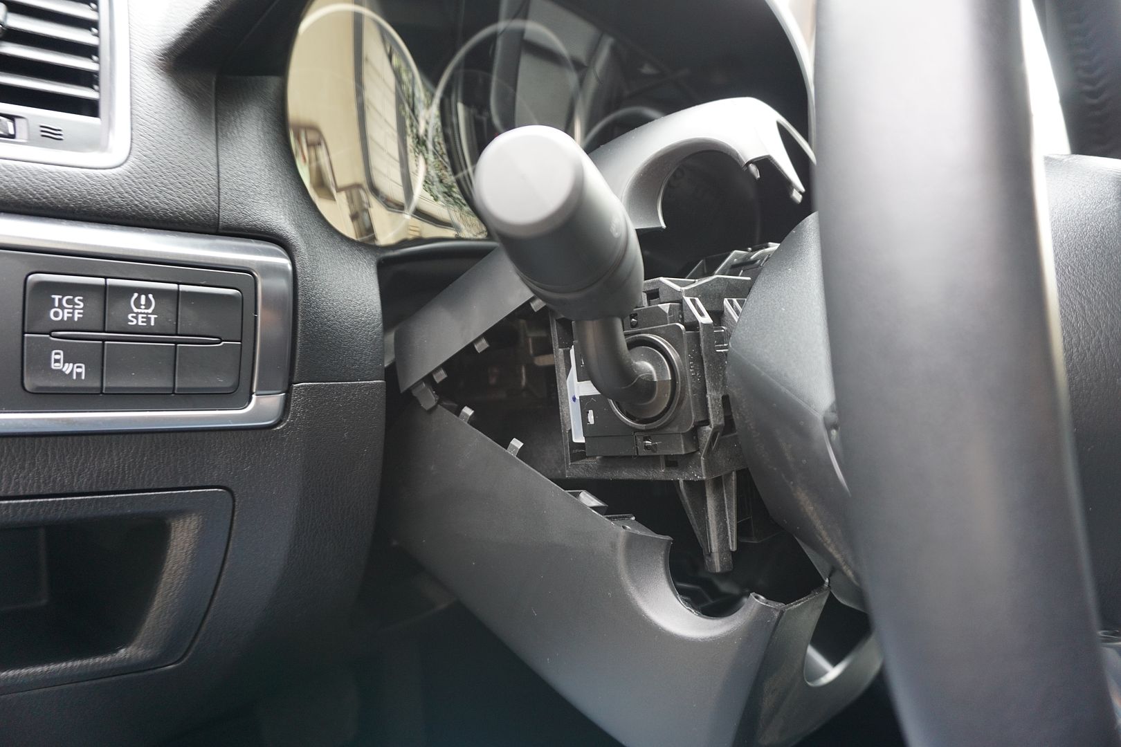
7) Then I moved the bottom portion to the side.
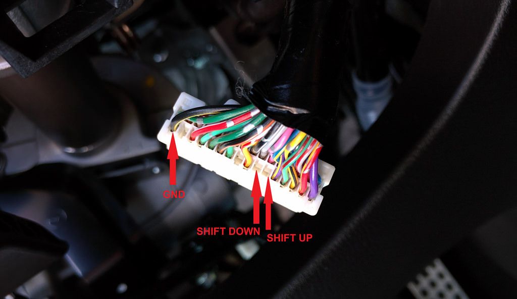
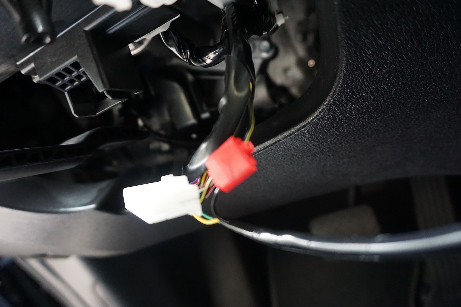
8) I pulled the clockspring connector and inserted the three wires of the paddle shift SW harness (K015-V7-481). (One Photo borrowed from member “Farenheight”)
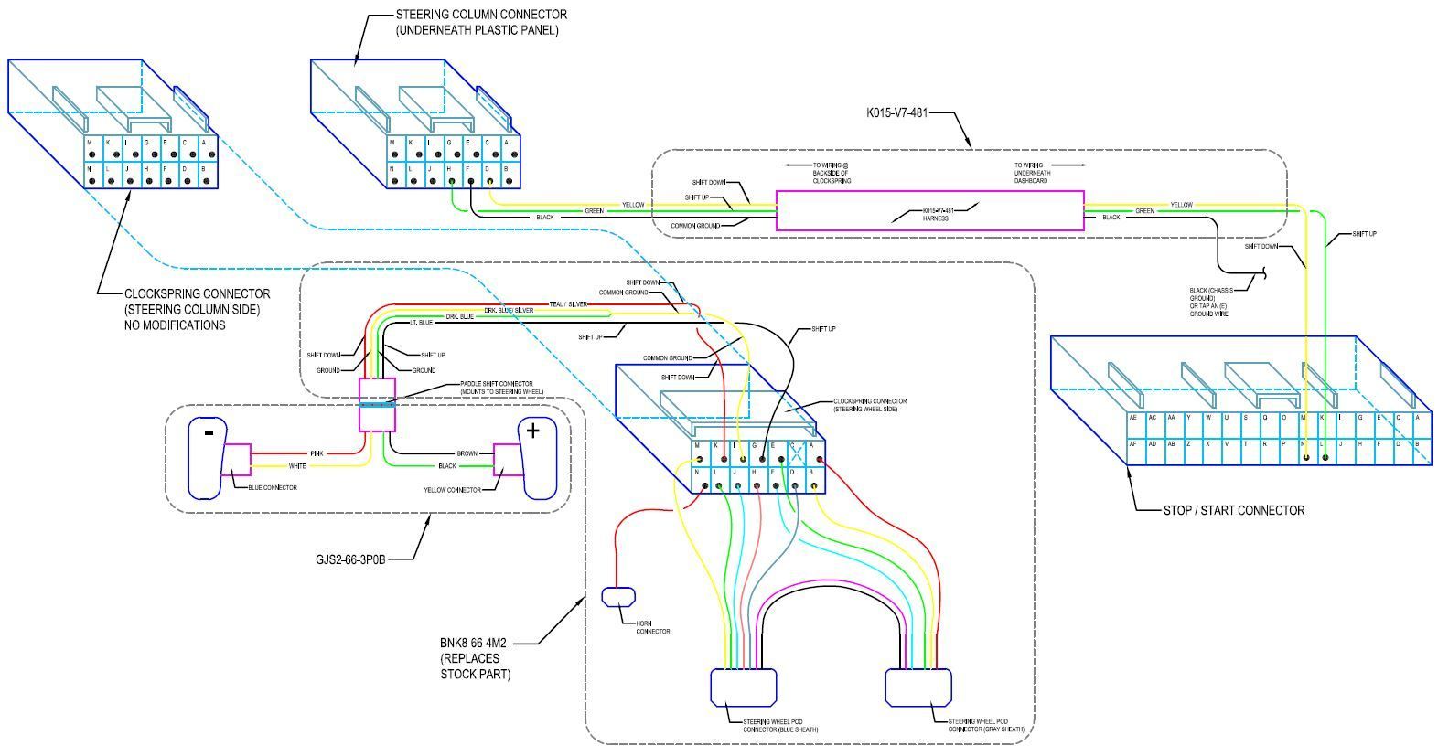
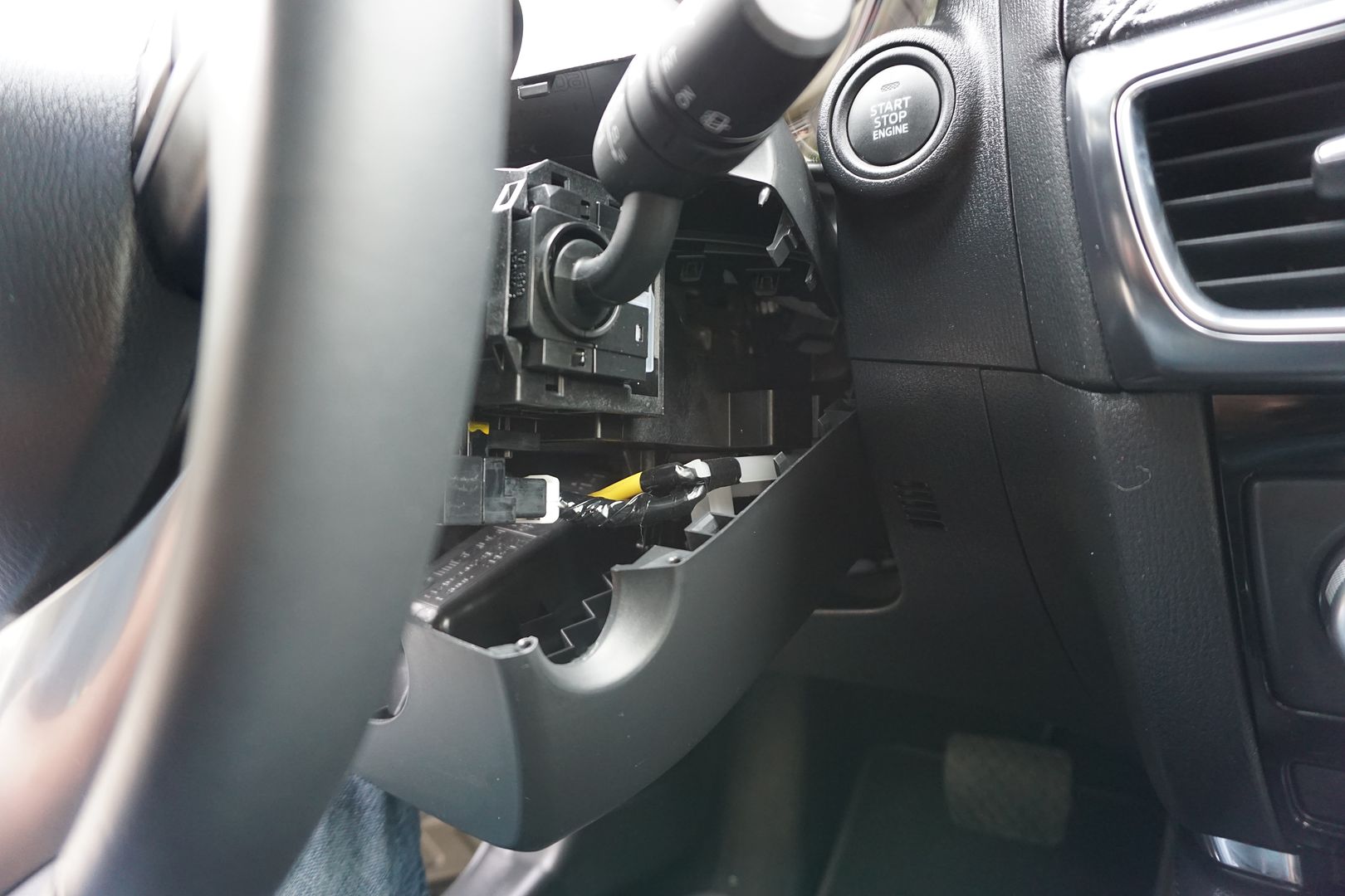
9) I pulled the vehicle connector near the start stop switch, and inserted the two shift wires into that connector. (K015-V7-481). (Photo borrowed from member “Farenheight”)
10) The remaining wire was the ground cable. I attached it to the existing ground in the harness or I could have extended it and attached it to the ground lug on the chassis frame next to the start stop switch.
11) I tucked the wiring in so as not to conflict with anything, re-wrapped the harness with electrical tape (since I removed some of it for access).
12) I used the provided zip ties as necessary to tuck this away.
13) Then I re-installed the top and bottom portions of the steering column cover and the two screws holding it together.
14) At this point I went back to the bench, got the steering wheel and placed it back on the shaft,
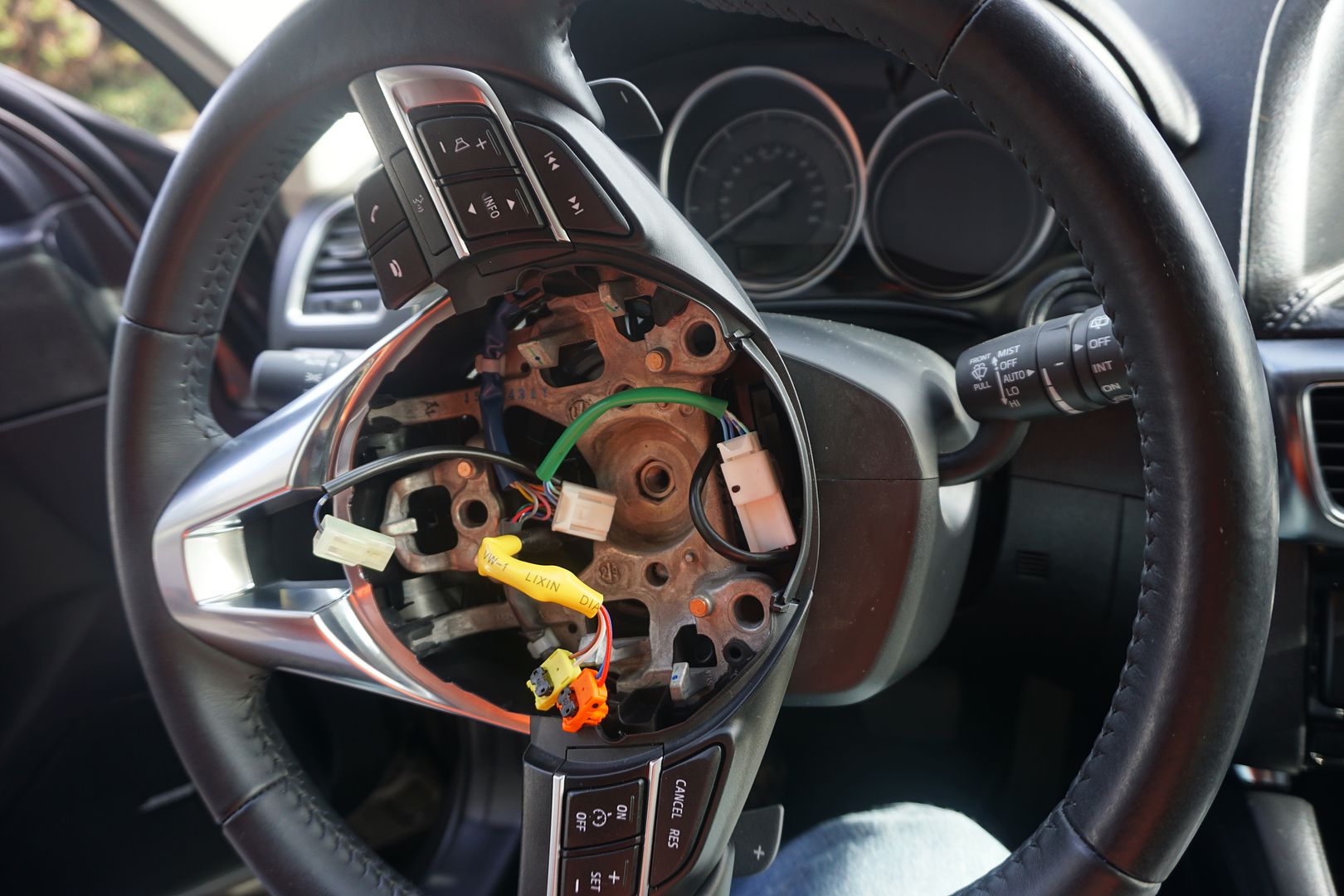
15) lined it up and connected the wiring (BNK8-66-4M2) to the clockspring,
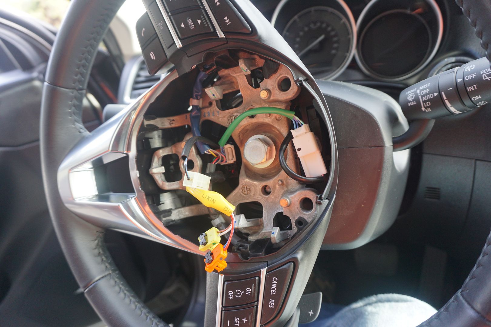
16) Then I inserted the new nut (9YA0-11-003A or the nut that comes with D10J-V7-480), and tightened the nut to the specified torque in the shop manual (41-54NM).
17) Then I re-connected the two power wires for the airbag, the horn wire (which is also attached to the airbag) and then placed the airbag gently onto the steering wheel, lining up the pins with their slots. Lastly, I pressed it into place until it locked.
18) Lastly, I re-connected the negative battery cable, started the car, put it in manual and tested the paddles for correct operation.
19) And that was it. Paddle shift completed.
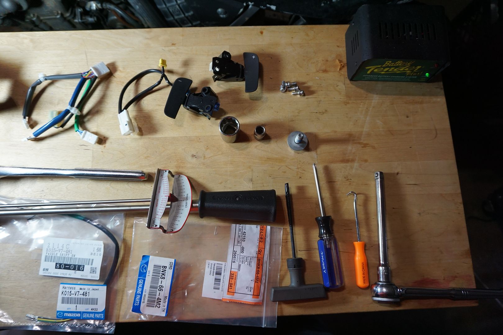
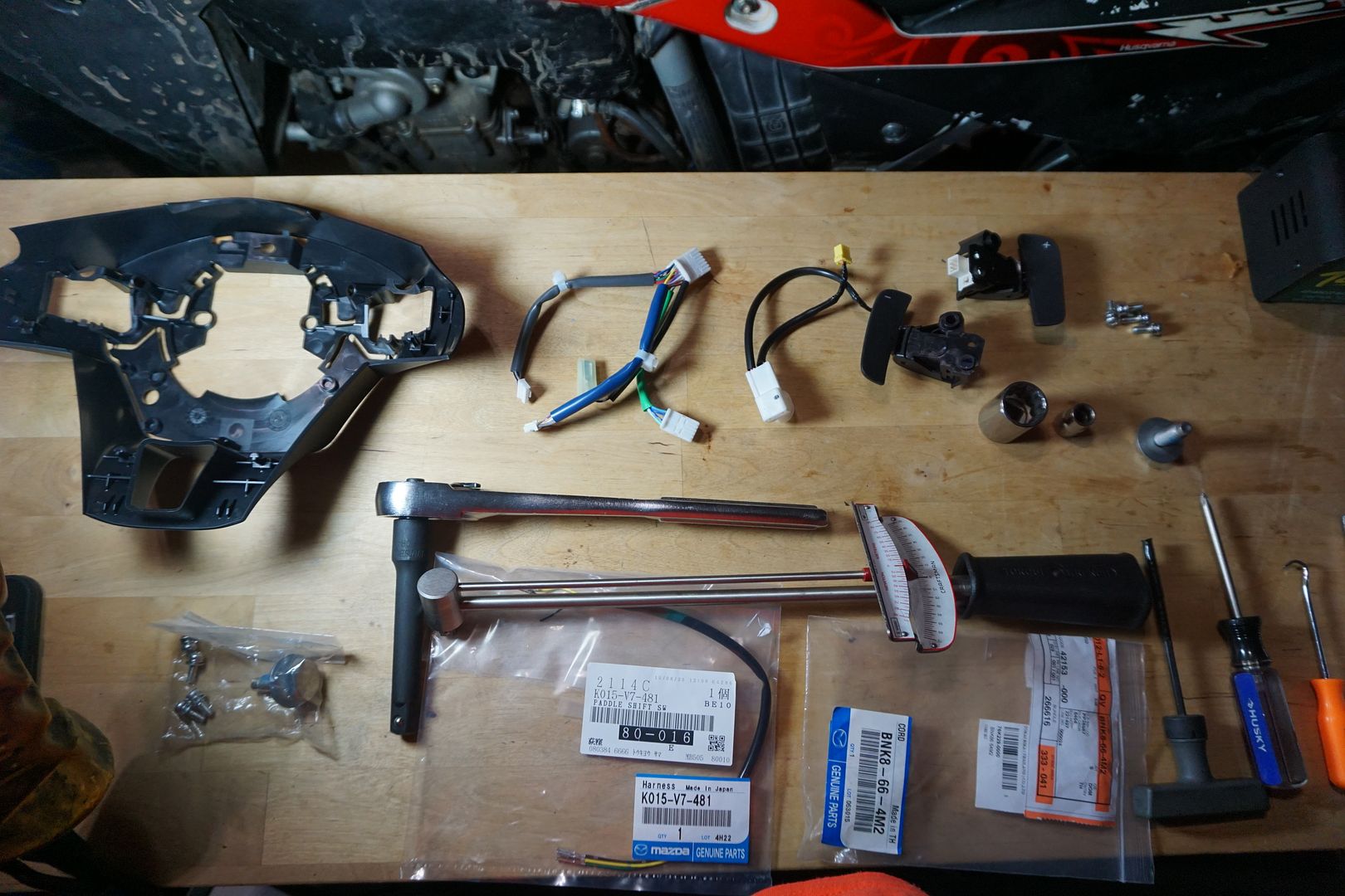
Also, see below for the majority of the parts and tools I used for this install.
2016 Mazda CX-5 –A/T, Grand Touring Model, Tech Package, AWD, Navigation (NO iActivesense)
This write-up describes how I installed the JDM Mazda paddle shifters onto this particular USA spec. model. Other models may vary, your experience may vary. This is simply a chronicle of how I completed this task. If you choose to do the same, the responsibility for your actions lie with you alone.
Also, I want to give credit where it’s due. I was only able to do this because of the thread in the “Engine and Transmission” Forum and with the insight, links and photos of members like Svshootingstar, Farenheight and Berner to name a few. Everyone who added to that thread has also helped make this one. Since I was able to do this with the help of others, I figured I’d contribute to the board by putting it all together in one place.
*Virtually all automotive wiring harnesses have some sort of locking mechanism the requires locking/unlocking prior to insertion/removal of wiring. It is solely your responsibility to correctly install any wiring on your own vehicle. If you think otherwise, pay someone to do it for you*
Parts Purchased:
Source: www.oemmazdaparts.com
GJS2-66-3P0B - Paddle Switch (came with its own wiring sub-harness)

BNK8-66-4M2 - Wire (Connectors for the paddles & OEM steering wheel pods)

BHN9-32-750 - Parts Set, Steering Wheel (small screws for steering wheel) **If ordering D10J-V7-480 from Japanparts below, this is not needed**
9YA0-11-003A or 007 – Steering Wheel Bolt (Bolt that holds the steering wheel in place) **If ordering D10J-V7-480 from Japanparts below, this is not needed**
www.japanparts.com (Special Order – Not listed on their website)
K015-V7-481 Paddle Shift SW Harness (note this item came with two identical harnesses, one end of the harness (vehicle side) is different. On one, the prongs are the short type, and on the other they are the long type. My vehicle used the long version).

D10J-V7-480 - Rear Cover + Small screws for steering wheel + Steering Wheel Bolt (these parts came as a set under this one part order). This also came with a set of instructions for installation (in Japanese).


Tools Used:
Long Hex (I wrapped this in electrical tape for this project in order to help avoid conducting electricity when working on the airbag).
Phillips screwdriver
Torque wrench
Socket 21mm, 10mm
Dental picks
X-acto knife
Disassembly Steps:
1) Disconnect negative battery terminal

2) To remove the airbag one needs to insert a long thin tool into each of the three service holes in order to unlock it from the steering wheel. I used hex tool wrapped in electrical tape. (Refer to the shop manual). I rotated the steering wheel to access all of the holes, one at a time. You can only access them when they are at the top of the steering column.


3) Once all three pins have been unlocked, I gently moved the airbag away from the wheel just far enough to gain access to the wires connecting it to the car. Disconnecting these wires from the harness freed the airbag for removal. I used a pick to pull straight up on the black portion of the connector. This can be pulled completely off, but it is not required. Then I grasped the connector with my fingers and pulled it away from the airbag. Of the three photos below, the first photo shows the connectors unlocked and ready to be pulled from the airbag, the second photo shows the connectors locked in place, and the last photo shows the connectors fully removed.


3.1) I used my fingers to remove the horn connector next.
4) Once all connections were removed, I placed the airbag someplace safe to avoid accidental deployment.
5) Use the (21mm) socket and a ratcheting wrench to remove the bolt holding the steering wheel in place.

6) I discarded the bolt, as I’ve read that it is intended as a “one time torque” bolt. It will be replaced later.
7) I made a note of the direction that the steering wheel was facing when I removed the nut to be sure I’d place it back in the exact same orientation.

8) I then disconnected the existing wheel side pod harnesses from the main vehicle harness.

9) I removed the steering wheel from the vehicle and placed it on my workbench.

10) I removed the left side pod that holds the hands free & stereo buttons from the wheel. It comes off by sliding the plastic tab to the left and pulling gently/ firmly straight away from the wheel.

11) Then I removed the right side pod in a similar manner to the left.

12) Then I removed the wiring from both pods. Be careful to release the locking tab before pulling on the connector.

13) Lastly, I removed the rear cover by pulling the plastic tabs away from the main part of the steering wheel and the pulling off the cover.

14) This leaves you with the base steering wheel.

Disassembly is now complete. It’s time for re-assembly.
Assembly Steps:
1) I placed the wiring attached to the paddles themselves (GJS2-66-3P0B) into the slots provided on the new rear cover (D10J-V7-480).

2) I then placed each paddle in its place and secured it with the two screws included in the kit (D10J-V7-480). The steering wheel was already pre-drilled and tapped for these screws.

3) Afterwards, I attached the wiring harness (BNK8-66-4M2) to the paddles wiring harness (GJS2-66-3P0B) and routed it inside the steering wheel hub as shown above.
4) Then I re-attached both side pods as indicated and put the wheel aside for the moment.

5) Then I went back to the car and removed the two screws holding the bottom portion of the steering column cover in place.

6) I slightly pushed forward and up on the top portion of the steering column cover to open it up.


7) Then I moved the bottom portion to the side.
8) I pulled the clockspring connector and inserted the three wires of the paddle shift SW harness (K015-V7-481). (One Photo borrowed from member “Farenheight”)


9) I pulled the vehicle connector near the start stop switch, and inserted the two shift wires into that connector. (K015-V7-481). (Photo borrowed from member “Farenheight”)


10) The remaining wire was the ground cable. I attached it to the existing ground in the harness or I could have extended it and attached it to the ground lug on the chassis frame next to the start stop switch.

11) I tucked the wiring in so as not to conflict with anything, re-wrapped the harness with electrical tape (since I removed some of it for access).
12) I used the provided zip ties as necessary to tuck this away.
13) Then I re-installed the top and bottom portions of the steering column cover and the two screws holding it together.
14) At this point I went back to the bench, got the steering wheel and placed it back on the shaft,

15) lined it up and connected the wiring (BNK8-66-4M2) to the clockspring,

16) Then I inserted the new nut (9YA0-11-003A or the nut that comes with D10J-V7-480), and tightened the nut to the specified torque in the shop manual (41-54NM).

17) Then I re-connected the two power wires for the airbag, the horn wire (which is also attached to the airbag) and then placed the airbag gently onto the steering wheel, lining up the pins with their slots. Lastly, I pressed it into place until it locked.


18) Lastly, I re-connected the negative battery cable, started the car, put it in manual and tested the paddles for correct operation.
19) And that was it. Paddle shift completed.
Also, see below for the majority of the parts and tools I used for this install.


Last edited: