
- :
- FC, FE, Mazda5
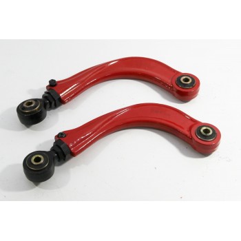
The Mazda5 tends to have too much negative camber which will eat through rear tires. When I got our '06 aligned, the rear was at around -2.5 deg, way too much! I decided to replace the stock upper camber link with an adjustable part to preserve the tires. First step - purchase adjustable rear camber link
http://www.speedyracer.com/Ford-Focus-Mazda-35-Adjustable-Rear-Camber-Kit
To actually install the link, you need to drop the rear subframe down to get access to the inner bolts. I had tried to swap them out earlier in the winter, but these bolts can only back out about 2" before hitting an exhaust hanger welded to the body on one side, and part of the fuel filler on the other. Put a jack up under the center of the subframe to support it as you free it from the body. The rear subframe is held on with 6 bolts, and then the top nuts for the rear shocks. Remove the rear-most bolts (in the middle of the spring), remove the inner front bolts (located off of the towers that the upper camber links bolt to), and loosen but don't remove the outer front bolts.

Once you unbolt the top of the struts from the body, you can then tilt the back of the subframe downwards, getting access to the heads of the bolts holding the inner end of the camber link to the subframe.


Support the hub on the side that you are working on, since as soon as you remove that bolt, the hub will want to flop outward, tugging on the brake line (which you DEFINITELY want to avoid. Having brakes is good!). The wheel & tire from that side can work, as could another jack or jack stand. Before removing that inner bolt, break loose the outer one while it's still held to the car so that you can just un-thread it without applying too much force later.

At this point, you can just remove the outer bolt, then the camber link. Now, time for some math! I had 2.5 deg of negative camber, and wanted around 1 degree, so needed to add 1.5 deg. A rough measurement from the approximate lower axis (lining up the bolt for the lower arm with the bottom spring perch & the toe control arm's bolt) that the hub pivots around up to the mounting point for the camber link was 190mm (green in drawing), and the existing length was 285mm. Adding 1.5 deg of camber meant that I needed to add 5mm to the length of the link. This is also end-to-end linear length, not additional length of threads in the adjustment, since the link itself (purple) is curved.

So, move the adjuster on the new linkages to get 290mm between the bolt holes (measure from the middle to middle, left-edge to left-edge, or right-edge to right-edge of the bolt holes). Tighten down the lock-nut and the allen-head to hold the adjustment.
Remember to use loc-tite on all the suspension mounting bolts, and I used anti-seize on the subframe mounting bolts to make sure that they wouldn't stick next time. I cleaned off the spots where the subframe touches the body to keep from trapping dirt & grit in there that could later form more rust, and could possibly allow some misalignment.
Overall, this took about 3 hours total with basic hand tools in the apartment parking lot, although some of that time was finding the inner front mounting bolts - i forgot about them initially.
5mm actually took out about 1.2 degrees - some of this is because the lower axis that the hub rotates around isn't flat, so some adjustment of the camber link actually changes the toe slightly. Also, I was estimating a lot of the angles involved in the math, so things could be off a little bit. However, 1.3 deg negative camber in back isn't bad, and now that I know that 5mm = 1.2 deg of change, I can go back in and readjust.
http://www.speedyracer.com/Ford-Focus-Mazda-35-Adjustable-Rear-Camber-Kit
To actually install the link, you need to drop the rear subframe down to get access to the inner bolts. I had tried to swap them out earlier in the winter, but these bolts can only back out about 2" before hitting an exhaust hanger welded to the body on one side, and part of the fuel filler on the other. Put a jack up under the center of the subframe to support it as you free it from the body. The rear subframe is held on with 6 bolts, and then the top nuts for the rear shocks. Remove the rear-most bolts (in the middle of the spring), remove the inner front bolts (located off of the towers that the upper camber links bolt to), and loosen but don't remove the outer front bolts.
Once you unbolt the top of the struts from the body, you can then tilt the back of the subframe downwards, getting access to the heads of the bolts holding the inner end of the camber link to the subframe.
Support the hub on the side that you are working on, since as soon as you remove that bolt, the hub will want to flop outward, tugging on the brake line (which you DEFINITELY want to avoid. Having brakes is good!). The wheel & tire from that side can work, as could another jack or jack stand. Before removing that inner bolt, break loose the outer one while it's still held to the car so that you can just un-thread it without applying too much force later.
At this point, you can just remove the outer bolt, then the camber link. Now, time for some math! I had 2.5 deg of negative camber, and wanted around 1 degree, so needed to add 1.5 deg. A rough measurement from the approximate lower axis (lining up the bolt for the lower arm with the bottom spring perch & the toe control arm's bolt) that the hub pivots around up to the mounting point for the camber link was 190mm (green in drawing), and the existing length was 285mm. Adding 1.5 deg of camber meant that I needed to add 5mm to the length of the link. This is also end-to-end linear length, not additional length of threads in the adjustment, since the link itself (purple) is curved.
So, move the adjuster on the new linkages to get 290mm between the bolt holes (measure from the middle to middle, left-edge to left-edge, or right-edge to right-edge of the bolt holes). Tighten down the lock-nut and the allen-head to hold the adjustment.
Remember to use loc-tite on all the suspension mounting bolts, and I used anti-seize on the subframe mounting bolts to make sure that they wouldn't stick next time. I cleaned off the spots where the subframe touches the body to keep from trapping dirt & grit in there that could later form more rust, and could possibly allow some misalignment.
Overall, this took about 3 hours total with basic hand tools in the apartment parking lot, although some of that time was finding the inner front mounting bolts - i forgot about them initially.
5mm actually took out about 1.2 degrees - some of this is because the lower axis that the hub rotates around isn't flat, so some adjustment of the camber link actually changes the toe slightly. Also, I was estimating a lot of the angles involved in the math, so things could be off a little bit. However, 1.3 deg negative camber in back isn't bad, and now that I know that 5mm = 1.2 deg of change, I can go back in and readjust.
