2013-2015 CX-5 Bose wiring diagram. What to tap to avoid Bose processing.

Schwacofer

Member
:
2014 Mazda CX-5 Touring
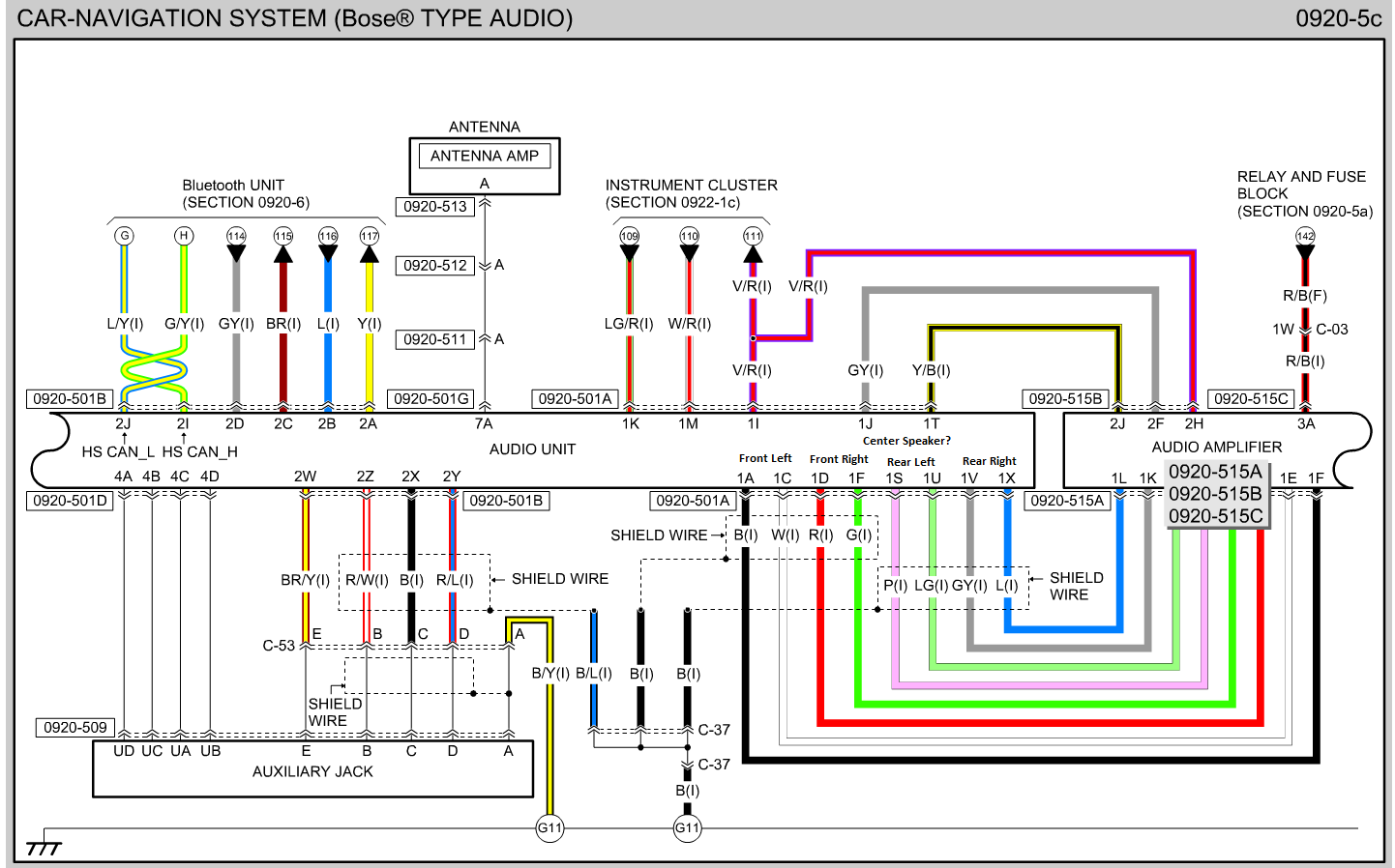
Hello, like many of us I want to upgrade my stereo in my Bose equipped CX-5. I personally do not want to change the head unit. From reading and searching many threads here and other places, tapping the speaker wires after the Bose amp will yield mixed results at best and still retain all the Bose processing. I think that this image will better illustrate what tap in order to make the best of the situation. I have not tested any of this and it comes from trying to peice together information from other posts and by comparing the various wiring diagrams.

1A+ and 1C- = Front Left
1D+ and 1F- = Front Right
1S+ and 1U- = Rear Left
1V+ and 1X- = Rear Right

These wire locations match perfectly to the locations on the 6 speaker non-Bose system. However the colors are listed to be different. Polarity should be the same.

I think that 1J and 1T will be the center speaker. Its the only other set of wires that would also go to the Bose amp and there match no other CX-5 Stereo. But this could use conformation.

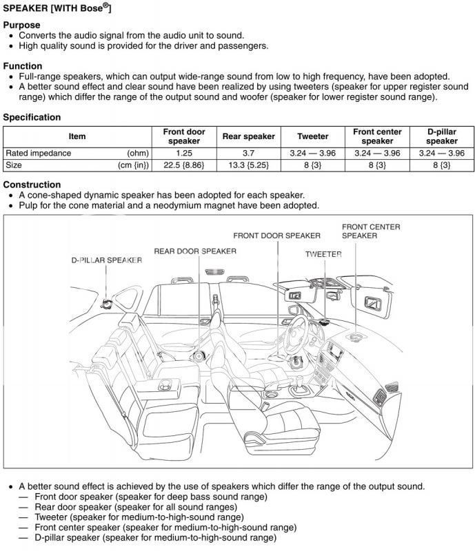
The rear D pillar speakers do not have a corresponding from the audio unit output. Bose looks to have just duplicated the existing rear output.

aMnzz9I.png
 
I questioned this in the thread I made as well. Not sure if anyone ever provided an answer. Hopefully someone can confirm.
 
I've installed an aftermarket head unit on a bose cx-5 - but using the bose amp. In essence, I've done the reverse of what you are trying to do - in both cases, the line level speaker wires need to be identified. In this thread: http://www.mazdas247.com/forum/showthread.php?123840616-Pioneer-AVH-4000-NEX-Install, on the first post, there's an attachment (interconnects.zip) that contains a spreadsheet. That spreadsheet contains the information you need by documenting the proper wires from the HU side of the harness. (Far left side of the spreadsheet.)

Keep in mind that, on the Bose systems, these are low level outputs - NOT speaker level. So, if you are replacing the amp, they should be suitable for direct connection.

I _think_ that the dash center channel is created as a result of processing in the bose amp (based on a config setting on the HU and not a direct output from the head unit.)
 
Keep in mind that, on the Bose systems, these are low level outputs - NOT speaker level. So, if you are replacing the amp, they should be suitable for direct connection.

I'm not sure about that. RCA's are 1 copper conducting cable, wrapped in 1 copper shielding cable. The wiring diagrams don't show anything that makes me think you can just put a RCA end on it and have your interconnect ready to connect into your amp. Has anyone tried turning these into RCAs?

Here:

http://www.diymobileaudio.com/forum/2175412-post26.html

User Josby does state "you should be able to run from these to the RCA input of your amplifier and get a full-range signal that won't mess up whatever the Bose amplifier is trying to do, hopefully."

Mogami-W2330-Interconnect-Wire.jpg


I've been trying to Google and check ebay for differences between the units and from what I can see they are the same and interchangeable. Nothing that I can find says they are not compatible as replacement parts.

KJ01 66 DV0C seems to be the part number for the Head Unit in the Bose package.
 
I'm not sure about that. RCA's are 1 copper conducting cable, wrapped in 1 copper shielding cable.
It's still two conductors. The "shielding" in an typical RCA conductor is ground, and wired to the negative terminal.

For wiring my aftermarket radio to the bose amp, I used a couple of old RCA cables I had laying around and chopped them off about 6 inches from the connector. The RCA connector plugs into the HU and the free wires are attached to the car's harness: The "pin" of the RCA connector (which is the inner conductor of the cable) to the positive and the "shield" of the RCA connector (which is the shield of the cable) to the negative.

For the tiny length between the back of the HU and the car's harness, I could have just as easily soldered two wires to a plain RCA connector without any shielding whatsoever. (In fact, that probably would have been easier than the way I did it.)

Or.. I might be completely misinterpreting your response....

Are you saying that you aren't sure that they are low level outs? I'm basing THAT piece of info on the experience of others who have done the same thing before me. In particular, jlcpremier who (in that same thread I linked above) states:
IMPORTANT: If you have a Bose system in your CX-5, you have to wire RCAs to the RP4 harness as the Bose amp is designed to take low level input, and the wires from the Pioneer harness would be feeding it high level input. Make sure to connect the RCAs to the RP4 speaker wires and not the pioneer harness.
 
Last edited:
No, I think you are understanding what I said properly and corrected it.

So the Bose head unit sends low level signal, thanks for correcting my understanding. That's actually makes things easier I think. Any idea what pins 1J and 1T are for? There is also a shared shield wire of some sort (C-37 and connects to G-11?) not sure how to read that part of the schematic.
 
That's actually makes things easier I think. Any idea what pins 1J and 1T are for? There is also a shared shield wire of some sort (C-37 and connects to G-11?) not sure how to read that part of the schematic.
I could only take WAG's for 1J/1T. It's possible that they are for control lines - to turn on/off "centerpoint" and "audiopilot" features?

The shared shield could be just that: a grounded shield. Actually, a common grounded shield would make sense: Instead of using the line-level negative wires as a shield (which would be annoying, expensive, and space consuming in the car harnesses), they use a common grounded shield. It would perform the same (perhaps better) as using the line ground as shield.

(Keep in mind that I'm taking educated guesses on the shielded ground. My suggestion makes sense, but it might have some other purpose.)
 
Reading that spreadsheet I referenced, it's possible that 1J is an amp turn-on signal. That would leave 1T as some kind of control line for turning on/off amp features.
 
I could only take WAG's for 1J/1T. It's possible that they are for control lines - to turn on/off "centerpoint" and "audiopilot" features?

I don't think it's the AudioPilot Mic because those look to originate at the Bose amp and not the Head unit. Though my center speaker works, CenterPoint has never been able to be activated on my 14. But that would be related to the center speaker. I guess once I undertake my build I'll snip the wire and see what happens.

<EDIT> just saw your post about the amp turn on. I didn't even think about that. You are probably correct.

Plugs on the Bose Amp

0920-515A = AudioPilot MIC
0920-515B = L&R Tweeter, L&R Rear Speakers, L&R D pillar Speakers
0920-515C = L&R Door Speakers, Center speakers

Plugs on the Head Unit

0920-501A = All Speaker pre outs, Instrument cluster, amp turn on? (1J&1T) ONLY Connector you have to remove/splice
0920-501B = Aux & Bluetooth
0920-501D = Aux
0920-501G = Antenna Amp
 
The more I think about this, the more I think I realize some of the additional steps/difficulties.

The center channel and rear d-pillar signal probably is dictated by the Bose amp So If you remove the any of the the inputs from the head unit side. So if you wanted to let the Bose amp power those speakers you would be out of luck; since those secondary speakers will no longer have source from which their signal is derived from.

You could probably tap and split the signal form the head unit, and that would still get a signal to the Bose amp that it would process into the center channel and D pillar speakers. But then your input voltage would be weaker, and along with that overall volume form the speaker. Maybe even too weak to get a suitable signal to the new after market amps. To compensate you would then need to add in a signal processor that also boost the output voltage to the amps. I don't think its hard problem to solve, just another possible step to be aware off.
 
I don't think it's the AudioPilot Mic because
No.. not the mic. A control line for the HU to tell the amp to turn the centerpoint and audio pilot FEATURE on or off. (If the feature is turned off at the HU, the mic is ignored.) When you change setting on the HU, it has to communicate that setting change to the amp. I suspect that might be the purpose of 1T.

The center channel and rear d-pillar signal probably is dictated by the Bose amp So If you remove the any of the the inputs from the head unit side. So if you wanted to let the Bose amp power those speakers you would be out of luck; since those secondary speakers will no longer have source from which their signal is derived from.
Correct. However, I've been guessing that you intend to also change the speakers. Those speakers in the car might pair well enough with the bose amp, but I don't think they'd work as well with another amp.

As well, the bose amp already "knows" that the front speaker freqs should be split between mid-low (door) and mid-high (dash) freqs. I admit that I'm not versed enough in car amps to know how easy it would be to accomplish something similar with an aftermarket amp. I know you can usually split off a mono sub-woofer channel with an amp, but those door speakers are more mid-range to low. Can the cutoffs be set that high?

As for the rear, there'd be no help but to pull new wire for them if you wanted them separated.

Actually, I really don't understand those D-pillar speakers. They're mid-high freq (small) speakers, and stereo separation is MORE important at higher frequencies. My only guess (and it's really a guess because I haven't spent any time trying to pay attention) is that the bose amp reduces the volume to those D-pillar speakers enough that they only act as fillers... (I don't know the proper term - they act like the back wall of a concert hall that would bounce some of the sound back behind an audience. If that's how they're used, then I guess stereo separation would be a moot point.)
 
No.. not the mic. A control line for the HU to tell the amp to turn the centerpoint and audio pilot FEATURE on or off. (If the feature is turned off at the HU, the mic is ignored.) When you change setting on the HU, it has to communicate that setting change to the amp. I suspect that might be the purpose of 1T.

The mic is connected to the Amp. At least thatch what the wiring diagram says, at least the actual mic it self it not connected to the head unit. You are right that it could be the controls.

As well, the bose amp already "knows" that the front speaker freqs should be split between mid-low (door) and mid-high (dash) freqs. I admit that I'm not versed enough in car amps to know how easy it would be to accomplish something similar with an aftermarket amp. I know you can usually split off a mono sub-woofer channel with an amp, but those door speakers are more mid-range to low. Can the cutoffs be set that high?

I've already replaced all 3 of the dash speakers with Polk db351's. Home audio is my hobby, so I have a measurement mic and all that, and measured each speaker to get an idea of what the Bose xovers are. The dash speakers are crossed over pretty high, ~3k if I remember correctly, so they are fictionally tweeters. There isn't much midrange that comes out of them despite what Bose might call them. So for anyone that has upgraded their dash speakers on a Bose system, they are not being used within their full range. While I didnt measure them, the mids in the doors should be low passed about 3k.

Yeah the D Pillars look like they will also be a tweeter according to this. It's a bit odd.

post-528-0-48942400-1355576246_thumb_zps87190c39.jpg
 
Back