
So im selling my CX racing custom ms6 FMIC.
Im about to sell the car so im bringing her back to stock! I will need the stock TMIC in exchange for the FMIC im selling plus $325.00. and shipping of course!
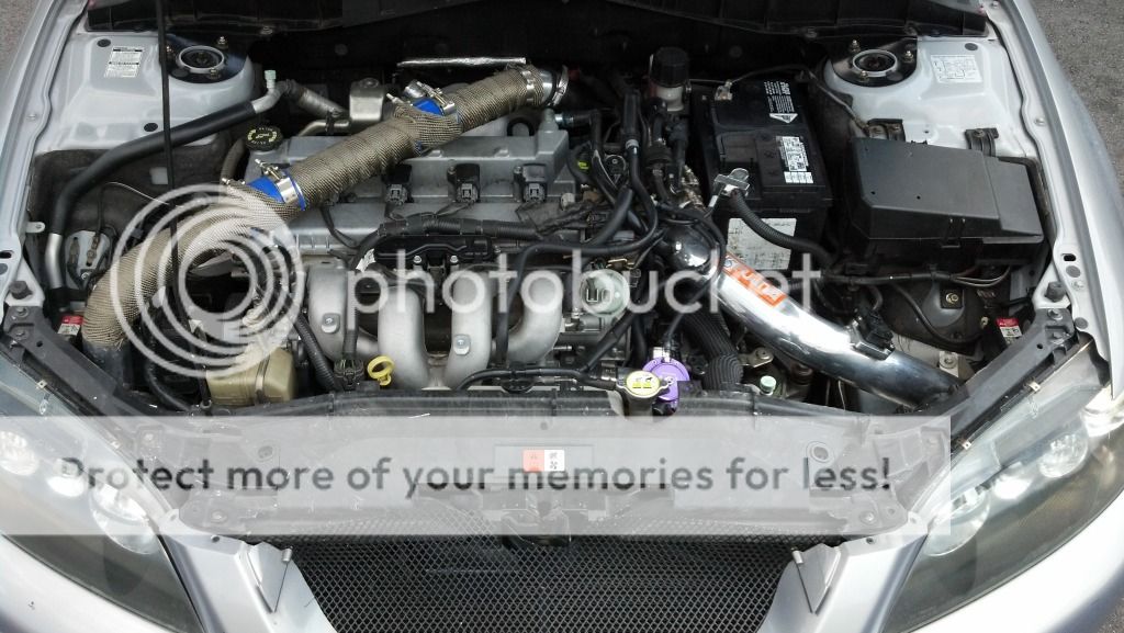
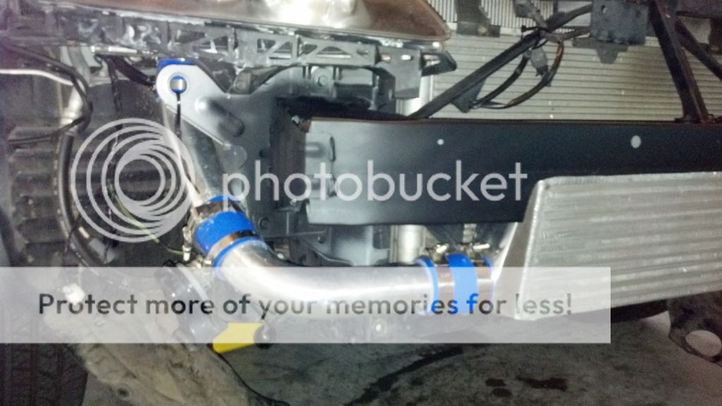
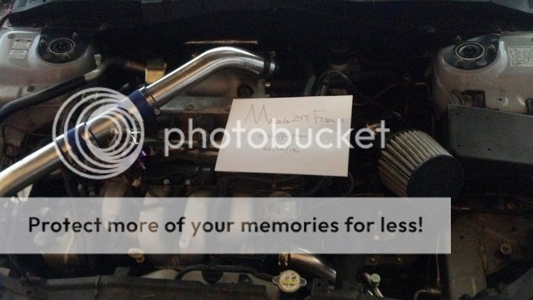
It comes with everything needed to do a direct swap. I did cut my crash bar for max efficiency but I have seen setups extremely similar to mine setup without cutting the crash bar.
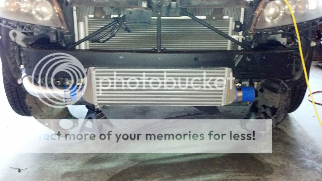
Bar & Plate Intercooler 28x7x2.5 inch - Inlet and outlet sizes: 2.5 inch
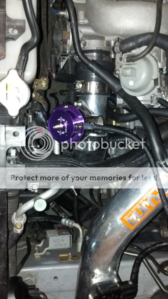
CX racing BOV
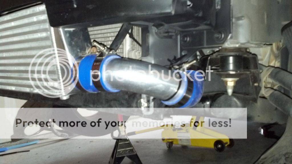
2.25in Hot/Cold Piping
Couples to stock turbo and stock intake manifold
All T-Clamps, Screw Clamps and 4ply silicone couplings needed are included
This is one of the most efficient designs if not the most efficient design out there! I did all of the math/ engineering and the building myself and can assure anyone that it will add power and efficiency to your setup. It has worked perfectly on my car and can be setup in many different ways for blow through setups or regular upgrade situations. Keep in mind im not a professional shop with all the best tools so some of my cuts could use finishing but it will work perfectly as is.
My setup has been now duplicated by many on the forums and tested by many proving the power gains!
All of the cutting and test fitting has been done as its been on my car for about 4500 miles. The intercooler and piping are all in good shape and work perfectly. BOV pipe and BOV will be included. This setup can be run recirculated or open. Ill even send some extra piping and couplers so you can run the setup however you like! Please contact me for details or questions.

COLLECTED DATA FOR DESIGN:
Stock TMIC
Core Size: 11 x 13 x 2 = 286
Air Inlet Size: 2 x (8 x 1.5 ducts) = 24
(Ducting mounted under hood)
DIY FMIC
Core Size: 22 x 7 x 2.5 = 385
(25.714 % Increase in core size over stock)
Air Inlet Size: 1 x (28 x 10) = 280
(Front Air dam 10X the contact area for air)
So as you can see even a budget DIY EBAY FMIC seems to be a WIN over the stock TMIC fo many reasons. The core size can be increased, along with the area in which air can travel to hit the IC, also heat soak (obviously). Now the qualtity of the parts im using is up in the air but i can always upgrade in the future to increase the efficiency of the setup. Also im hoping that Ill be able to keep my pipes cool enough to actually be utilizing that travel as additional cooling to the charged air by using heat wrap, tube blankets, turbo blanket, and i already have a vented hood that really keeps down ambient under the hood temps, especially in stop and go, or in the mountains. I also plan on directing and focusing the air still coming from the stock ducting system to cool the top pipe coming across the engine. Comments and concerns are welcome. I love working on cars and fabing things so Im sure i can tackle this, Im just excited to document it and see how it turns out!
Decided to start compiling some data..... please let me know if you have figures that suggest other wise. All of this is based off of information i have searched on the internet.....
Stock k04 @ 15.6 psi @ 5560 rpm cfm flow rate of 491 cfm
Stock k04 @ 19 Psi @ 5560 rpm cfm flow rate of 564 cfm
BNR stage 3 25% more efficient then stock which puts it at about 614 cfm
CXracing intercooler max cfm flow rate of 700 cfm
PIPING FLOW RATES-
2" piping
1.57 x 2 = 3.14 sq in
300 cfm = 156 mph = 0.20 mach
400 cfm = 208 mph = 0.27 mach
500 cfm = 261 mph = 0.34 mach
585 cfm max = 304 mph = 0.40 mach
2.25" piping
3.9740625 sq in = 1.98703125 x 2
300 cfm = 123 mph = 0.16 mach
400 cfm = 164 mph = 0.21 mach
500 cfm = 205 mph = 0.26 mach
600 cfm = 247 mph = 0.32 mach
700 cfm = 288 mph = 0.37 mach
740 cfm max = 304 mph = 0.40 mach
2.5" piping
4.90625 sq in = 2.453125 x 2
300 cfm = 100 mph = 0.13 mach
400 cfm = 133 mph = 0.17 mach
500 cfm = 166 mph = 0.21 mach
600 cfm = 200 mph = 0.26 mach
700 cfm = 233 mph = 0.30 mach
800 cfm = 266 mph = 0.34 mach
900 cfm = 300 mph = 0.39 mach
913 cfm max = 304 mph = 0.40 mach
*.4 Mach is the point at which air becomes turbulent and losses in efficiency start to occur exponentially. The key is to stay under that speed. You want to use the smallest piping possible that still flows enough to meet your needs. Larger than necessary piping increases lag time with no measurable gain
So if you look at my current setup of stock boost and turbo I should technically be running 2in piping for max inefficiency but the 2.25in piping is still in the GOOD range and will work for people running more then stock boost on the stock or upgraded turbo.
DESIGN- PIPE ROUTE AND ASSEMBLY
Turbo
2 to 2.25 Reducer 45 deg. Elbow Coupler
2.25 Pipe 30 deg. Bend + straight
2.25 Coupler
2.25 Straight Pipe
2.25 Coupler
2.25 Pipe 75 deg. Bend
2.25 Coupler
2.25 Pipe 45 deg. Bend + straight
2.25 Coupler
2.25 Pipe 75 Deg. Bend
2.25 to 2.5 Reducer Coupler
Intercooler
2.25 to 2.5 Reducer Coupler
2.25 Pipe 75 Deg. Bend
2.25- 45 Deg. Coupler
2.25 Pipe 30 Deg. Bend + Straight
2.25- 45 Deg. Coupler
2.25 BOV Flange Pipe
2.25 to 2.75 Reducer Coupler
Im about to sell the car so im bringing her back to stock! I will need the stock TMIC in exchange for the FMIC im selling plus $325.00. and shipping of course!
It comes with everything needed to do a direct swap. I did cut my crash bar for max efficiency but I have seen setups extremely similar to mine setup without cutting the crash bar.
Bar & Plate Intercooler 28x7x2.5 inch - Inlet and outlet sizes: 2.5 inch
CX racing BOV
2.25in Hot/Cold Piping
Couples to stock turbo and stock intake manifold
All T-Clamps, Screw Clamps and 4ply silicone couplings needed are included
This is one of the most efficient designs if not the most efficient design out there! I did all of the math/ engineering and the building myself and can assure anyone that it will add power and efficiency to your setup. It has worked perfectly on my car and can be setup in many different ways for blow through setups or regular upgrade situations. Keep in mind im not a professional shop with all the best tools so some of my cuts could use finishing but it will work perfectly as is.
My setup has been now duplicated by many on the forums and tested by many proving the power gains!
All of the cutting and test fitting has been done as its been on my car for about 4500 miles. The intercooler and piping are all in good shape and work perfectly. BOV pipe and BOV will be included. This setup can be run recirculated or open. Ill even send some extra piping and couplers so you can run the setup however you like! Please contact me for details or questions.
COLLECTED DATA FOR DESIGN:
Stock TMIC
Core Size: 11 x 13 x 2 = 286
Air Inlet Size: 2 x (8 x 1.5 ducts) = 24
(Ducting mounted under hood)
DIY FMIC
Core Size: 22 x 7 x 2.5 = 385
(25.714 % Increase in core size over stock)
Air Inlet Size: 1 x (28 x 10) = 280
(Front Air dam 10X the contact area for air)
So as you can see even a budget DIY EBAY FMIC seems to be a WIN over the stock TMIC fo many reasons. The core size can be increased, along with the area in which air can travel to hit the IC, also heat soak (obviously). Now the qualtity of the parts im using is up in the air but i can always upgrade in the future to increase the efficiency of the setup. Also im hoping that Ill be able to keep my pipes cool enough to actually be utilizing that travel as additional cooling to the charged air by using heat wrap, tube blankets, turbo blanket, and i already have a vented hood that really keeps down ambient under the hood temps, especially in stop and go, or in the mountains. I also plan on directing and focusing the air still coming from the stock ducting system to cool the top pipe coming across the engine. Comments and concerns are welcome. I love working on cars and fabing things so Im sure i can tackle this, Im just excited to document it and see how it turns out!
Decided to start compiling some data..... please let me know if you have figures that suggest other wise. All of this is based off of information i have searched on the internet.....
Stock k04 @ 15.6 psi @ 5560 rpm cfm flow rate of 491 cfm
Stock k04 @ 19 Psi @ 5560 rpm cfm flow rate of 564 cfm
BNR stage 3 25% more efficient then stock which puts it at about 614 cfm
CXracing intercooler max cfm flow rate of 700 cfm
PIPING FLOW RATES-
2" piping
1.57 x 2 = 3.14 sq in
300 cfm = 156 mph = 0.20 mach
400 cfm = 208 mph = 0.27 mach
500 cfm = 261 mph = 0.34 mach
585 cfm max = 304 mph = 0.40 mach
2.25" piping
3.9740625 sq in = 1.98703125 x 2
300 cfm = 123 mph = 0.16 mach
400 cfm = 164 mph = 0.21 mach
500 cfm = 205 mph = 0.26 mach
600 cfm = 247 mph = 0.32 mach
700 cfm = 288 mph = 0.37 mach
740 cfm max = 304 mph = 0.40 mach
2.5" piping
4.90625 sq in = 2.453125 x 2
300 cfm = 100 mph = 0.13 mach
400 cfm = 133 mph = 0.17 mach
500 cfm = 166 mph = 0.21 mach
600 cfm = 200 mph = 0.26 mach
700 cfm = 233 mph = 0.30 mach
800 cfm = 266 mph = 0.34 mach
900 cfm = 300 mph = 0.39 mach
913 cfm max = 304 mph = 0.40 mach
*.4 Mach is the point at which air becomes turbulent and losses in efficiency start to occur exponentially. The key is to stay under that speed. You want to use the smallest piping possible that still flows enough to meet your needs. Larger than necessary piping increases lag time with no measurable gain
So if you look at my current setup of stock boost and turbo I should technically be running 2in piping for max inefficiency but the 2.25in piping is still in the GOOD range and will work for people running more then stock boost on the stock or upgraded turbo.
DESIGN- PIPE ROUTE AND ASSEMBLY
Turbo
2 to 2.25 Reducer 45 deg. Elbow Coupler
2.25 Pipe 30 deg. Bend + straight
2.25 Coupler
2.25 Straight Pipe
2.25 Coupler
2.25 Pipe 75 deg. Bend
2.25 Coupler
2.25 Pipe 45 deg. Bend + straight
2.25 Coupler
2.25 Pipe 75 Deg. Bend
2.25 to 2.5 Reducer Coupler
Intercooler
2.25 to 2.5 Reducer Coupler
2.25 Pipe 75 Deg. Bend
2.25- 45 Deg. Coupler
2.25 Pipe 30 Deg. Bend + Straight
2.25- 45 Deg. Coupler
2.25 BOV Flange Pipe
2.25 to 2.75 Reducer Coupler
Last edited:
")