Add LED Cargo Lighting

Franzy

Member
:
2006 Mazda5 - BlueBamba
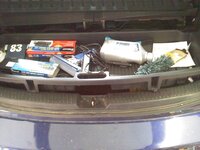
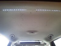
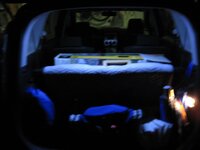
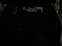
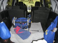
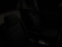
I have an 06'. As many of you 5'ers know, the cargo area lighting is down right whimpy, pathetic, crappy.... yadda yadda yadda.(dark)

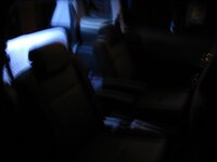
Here's the solution. As I told another member here; I wanted useful light, not going for the bling thing. I also wanted it to be as inconspicuous as possible.
There are other LED strips out there, so it's your call on which one you use.

All of you can do this relatively simple upgrade for about $40.00 (depending on the type of LED setup you buy)(eek2)

So here we go. Here's what you need.
-#2 phillips screwdriver.
-#2 or 3 slotted screwdriver.
- 10mm socket.
- A wire stripper tool.
- Hot glue gun (I prefer high temp).
- smallest slotted jewelers screwdriver (Like the ones at the dollar store).
- A good sharp knife or box cutter (very minimal use. Two 1/8" notches).
- 4 ft of 22AWG or 20AWG speaker wire. (I used 22AWG for this project).
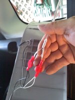
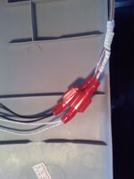
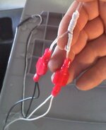
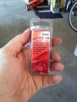
- 2 sets of 18-22AWG Male & Female insulated connectors (The red ones).
- Regular Isopropyl alcohol.
- A few Q-tips.
- a very small piece of course sand paper. 2"x2" will do.
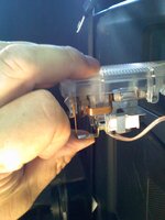
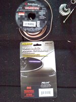
- Your LED strips (or strip). I used 2 "PILOT CZ-3008W PHANTOM LED
STRIP" from Auto Zone. I have seen these at Pep Boys also. They are
12" White Light and very low profile.
- Some good jams!
- Some beef jerky!

If you have a small narrow set of needle nose pliers, that will help also during the 1 step they could be used.

Now on to the disassembly and prep!

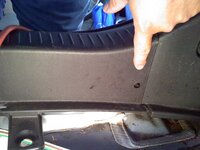
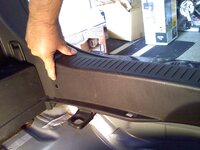
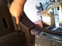
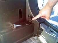
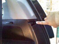
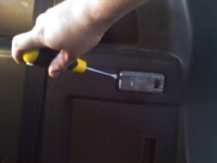
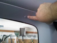
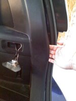
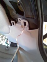
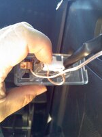
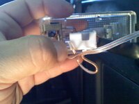
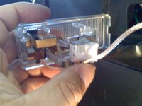
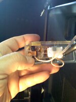
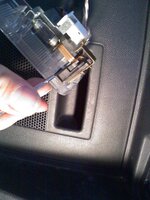
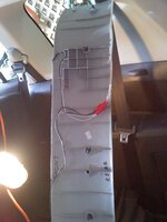
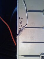
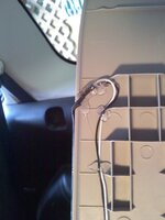
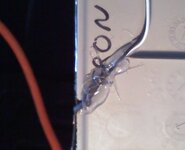
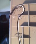
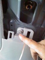
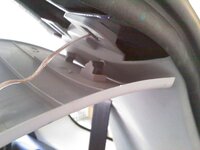
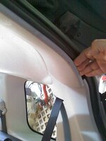
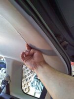
1 - At the very rear of the cargo area, up top, remove the crossover fascia piece. Be sure to grab from the front and back. start at one side or the other (it doesn't matter) and pull it straight down. It has 6 connection points along it's width. Go ahead and mark which way is front and which way is back (on the inside). This will save you a lot of time later, especially if your not used to disassembly.
 

Attachments

  • 22AWG speaker wire & LED type.jpg
    22AWG speaker wire & LED type.jpg
    425.6 KB · Views: 274
  • Male&Female Crimp connects.jpg
    Male&Female Crimp connects.jpg
    322.3 KB · Views: 229
  • Pull down crossover fascia.jpg
    Pull down crossover fascia.jpg
    378 KB · Views: 275
  • Grip from both sides.jpg
    Grip from both sides.jpg
    313.9 KB · Views: 279
  • LED Center.jpg
    LED Center.jpg
    247.1 KB · Views: 322
Last edited:
Panels removal and seperation

1 - Take the tray out

2 - Remove the pop-outs/pull-outs holding the plastic piece across the bottom
seal.

3 - Remove the tie down with a 10mm socket.

4 - Remove the phillips head screw on the right panel.

5 - On the upper pillar fascia, remove the pop-outs/pull-outs from the top.

6 - In the right rear window, remove the pop-outs/pull-outs from the top.

7 - Now take the slotted screwdriver and pop that measly little light out of the
panel, from the front of the light.
 

Attachments

  • Lt side pull out.jpg
    Lt side pull out.jpg
    533.6 KB · Views: 197
  • Remove tray.jpg
    Remove tray.jpg
    446.9 KB · Views: 204
  • Rt side pull out.jpg
    Rt side pull out.jpg
    385.5 KB · Views: 195
  • Tie down 1.jpg
    Tie down 1.jpg
    313.6 KB · Views: 184
  • Tie down 2.jpg
    Tie down 2.jpg
    345.9 KB · Views: 193
Panels removal and seperation 2

Continued.(lurk)
 

Attachments

  • Remove phillips screw.jpg
    Remove phillips screw.jpg
    339.2 KB · Views: 171
  • Remove pillar pop-out 1.jpg
    Remove pillar pop-out 1.jpg
    310.3 KB · Views: 160
  • Remove from front.jpg
    Remove from front.jpg
    201.1 KB · Views: 166
  • Remove this pop-out also.jpg
    Remove this pop-out also.jpg
    319.6 KB · Views: 168
  • Pull rear panel.jpg
    Pull rear panel.jpg
    285.1 KB · Views: 178
Panels removal and seperation 3

Still continued(lurk).

After you have seperated the panel and pillar from the back edge, go ahead and feed your wire through.

I am showing it here with my wires attached at the bottom already. The next post will show how it is attached to the switch.
 

Attachments

  • Pull piller fascia.jpg
    Pull piller fascia.jpg
    320.3 KB · Views: 169
  • Wire feed top of piller.jpg
    Wire feed top of piller.jpg
    284.6 KB · Views: 159
  • Wire feed 1.jpg
    Wire feed 1.jpg
    337.6 KB · Views: 165
  • Wire feed 2.jpg
    Wire feed 2.jpg
    311.2 KB · Views: 148
  • Popped out with wire.jpg
    Popped out with wire.jpg
    268.8 KB · Views: 186
Last edited:
Switch connection.

One thing to remember about LED's, is that they are only powered ONE WAY. (detect)It's not like the regular incandescent bulbs that can have the wires switched and as long as ones on "+" and the other on "-" it works. I'll show a couple of posts with this because it's the only way the switch will actuate both the LED's and the regular light at the same time. If you have them in reverse at the switch, you'll get an annoying result.

**** VERY IMPORTANT*** TWIST YOUR WIRE ENDS AFTER YOU STRIP THEM!
ALSO, DO NOT ATTACH THE WIRES ONLY TO THE WIRE HARNESS OR THE TWO WIRES THAT GO INTO THE WIRE HARNESS. THIS WILL SIMPLY KEEP YOUR LED'S ON ALL THE TIME!

View 1 shows the back of the switch with the White Harness Connector
(WHC) attached.

View 2 Shows the WHC slightly slid off of the two small blades it attaches to.
As you can see, I have a wire going into the hole of the bottom insert
on the harness. It is where the lower (or silverish) blade is going into
the harness.

View 3 Shows the wire inserted much clearer, into the harness.

After you insert the wire into the harness, then you simply slide the harness back on, with the wire in there, and it creates a compression connection, just as good as crimping.

Now for the other wire.

Views 1,3,4 & 5 Show the other wire going under the side piece of copper (on the switch) and then up and over the upper piece of copper. Be sure and strip about 1& 1/4" for this

(This is where the Needle-nose pliers and very small slotted jewelers screwdriver come in.) Be sure to wrap the body of these two with even simple scotch tape. This will keep you from shorting out the two poles. Don't worry though. The light will come on if you do. I did this like 20 times and never blew the fuse.

On this part of the switch, you will see that the entire copper throw, here, is somewhat stuck in a piece of plastic. There is some space there between the plastic and the copper throw. I routed the wire around the copper throw and then shoved the wire into that itty-bitty space, with the small slotted jewelers screwdriver, and came back around and tied the wire with the Needle-nose pliers.

Congrats, you have just accomplished the hardest part of the whole exercise. Some might want to use solder here, but if you don't have that or know how, this will work just as well.

I'm sure someone will come up with a better way of connecting that wire, but it'll work for now and for as long as I've been using it.
 

Attachments

  • Connector view 1.jpg
    Connector view 1.jpg
    333.4 KB · Views: 174
  • Connector view 2.jpg
    Connector view 2.jpg
    316.2 KB · Views: 157
  • Connector view 3.jpg
    Connector view 3.jpg
    343.7 KB · Views: 158
  • Connector view 4.jpg
    Connector view 4.jpg
    317.3 KB · Views: 160
  • Connector view 5.jpg
    Connector view 5.jpg
    332 KB · Views: 151
Last edited:
Switch connection 2

As you can see here, I have the top of the switch with the small slotted jewelers screwdriver there. It is in the spot where you will be pushing the wire into that space.

If all is right then here is what happens after all wires are connected.


Do not pop the light switch back in yet.

Now it's off to the crossover piece and fitting the LED's on it.
 

Attachments

  • Success test.jpg
    Success test.jpg
    295.5 KB · Views: 220
  • Switch wire View 1.jpg
    Switch wire View 1.jpg
    496 KB · Views: 185
Crossover piece prep & LED mounting

Sandpaper, alcohol, Q-tips & your cutting utensil needed now.

Cutting to be done as per the LED's you buy.


1 - On the front edge of the crossover piece, where the LED's will be, take the sandpaper (60 grit does nicely) and rough up the surface. Your only roughing up about 3/16" wide of surface, and you don't need to sand down much. (hear ya)The surface is too slick and if you have ever used Armor-all or something, your LED's won't stick right.(hear ya)

So Sand that small bit of surface and then make sure to clean it a few times with the alcohol and Q-tips.

2 - Pick your position on the upper front edge of the cross-over piece. Because my LED's had a bit of a direction to them, I mounted them with the pass through at the center and right.
(hear ya)CUT THE NOTCHES AT AN ANGLE(hear ya)!!! LED strips are not meant to be folded at direct 90 degree angles. 0 - 60 degree angles are your range typically.
 

Attachments

  • LED attached 2.jpg
    LED attached 2.jpg
    43.1 KB · Views: 188
  • Crossover 1.jpg
    Crossover 1.jpg
    325.1 KB · Views: 165
  • LED Center.jpg
    LED Center.jpg
    247.1 KB · Views: 160
  • LED Right.jpg
    LED Right.jpg
    304.4 KB · Views: 160
  • LED Center 2.jpg
    LED Center 2.jpg
    56.7 KB · Views: 176
Connecting wires up top.

After you have cut your notches and attached the LED's to the crossover piece, It's time to Hot Glue the Pass through points of the LED's. Pretty basic and simple. The Pics show it all. Now hurry up and wait for the Glue to cool down.

After the LED's are in place now; be sure your wire strands get twisted first, the white and black leads.

(five-0)(flame)***** Don't crimp anything yet*****(flame)

You should have your stripped LED wires and your stripped power wires (the speaker wire).

Test which one is lighting your LED's. The light on the regular Cargo light should be on at the same time.

As you can see from what I did; I just made use of something right there. I used a white twist-tie to show my wire to attach to the white wire from the LED's.
 

Attachments

  • LED Right 2.jpg
    LED Right 2.jpg
    130.3 KB · Views: 129
  • LED Center 2.jpg
    LED Center 2.jpg
    56.7 KB · Views: 138
  • All wires connected top.jpg
    All wires connected top.jpg
    339.8 KB · Views: 125
  • All wires connected top 2.jpg
    All wires connected top 2.jpg
    118 KB · Views: 136
  • Connection view 1.jpg
    Connection view 1.jpg
    265.3 KB · Views: 139
Last edited:
Crimping

This may be overkill for some, but I wanted to make the instructions for the novice.

Before crimping anything; test your lights all on for one last time, with your current wiring.

Use a Male and Female crimp connector on each side of the wiring:
- A Male and Female for the LED side.
- A Male and Female for the power side.

This will make sure that you don't cross them, should you ever need to unhook them.


Now that everything is connected, remember to Cable Tie your wires by the switch.
 

Attachments

  • Success test.jpg
    Success test.jpg
    295.5 KB · Views: 153
  • Connection view 1.jpg
    Connection view 1.jpg
    265.3 KB · Views: 135
  • All wires connected top 2.jpg
    All wires connected top 2.jpg
    118 KB · Views: 143
  • Cable tie & Cut.jpg
    Cable tie & Cut.jpg
    562.8 KB · Views: 146
Reassembling

(band2) Views 1 & 2
Go ahead and put the pillar top pull-out/pop-out back in first. You don't need to put it all back together just yet. This will save you from having to remove the crossover piece later.

(band2) Views 3 & 4
When putting your crossover piece back up; Start from the right side first. This way you'll be sure not to pinch your power wires. As you can see, it's just lining the insertion points up and popping the crossover piece in.

Keep testing the switch after panels or parts are attached to make sure the LED's and Light are going on together. This way if there's a problem you'll know that it happened with the last panel/part you attached.(bowdown).

I left the actual switch as the LAST THING I put back in. I wanted to make sure that everything else was OK on the reassembly first.

(headbang)(friday)Let me know if you need any more instructions.(friday)(headbang)
 

Attachments

  • Wire feed top of piller.jpg
    Wire feed top of piller.jpg
    284.6 KB · Views: 156
  • Pillar pop-out 1.jpg
    Pillar pop-out 1.jpg
    310.3 KB · Views: 160
  • Insert Rt side crossover first.jpg
    Insert Rt side crossover first.jpg
    380.8 KB · Views: 183
  • In Cargo area looking up.jpg
    In Cargo area looking up.jpg
    240.3 KB · Views: 284
Last edited:
Any way you can do a before and after nightime shot? I'm curious as to what kind of output these things do. I'm not sure I'd install a whole LED strip, but a couple 2 or 4 in some surface mount holders may be doable.
 
Night pics of LED on/off

A couple of the back

First one: All lights out

Second, Third & Forth are with the LED and Standard cargo light on.

Fifth is what you see with the flash of the camera on.
 

Attachments

  • IMG_0409.JPG
    IMG_0409.JPG
    458.6 KB · Views: 257
  • IMG_0408.JPG
    IMG_0408.JPG
    262.1 KB · Views: 213
  • IMG_0417.JPG
    IMG_0417.JPG
    480.8 KB · Views: 208
  • IMG_0418.JPG
    IMG_0418.JPG
    562.3 KB · Views: 193
  • IMG_0419.JPG
    IMG_0419.JPG
    854.6 KB · Views: 182
As seen in middle row.

The first pic is the 2nd row seats with their overhead light on only.

The next pic (Sorry it came out blurry) is with the 2nd row overhead light AND the rear LED lights on.

I put the camera on Night Shots, but it still didn't pick up enough light to do this justice.(headbang)

(2thumbs) I was, and still am, quite surprised by how much light you actually see at night from these lights.(2thumbs)

For $30.00 worth of lights (plus tax of course) I think I made out quite well.(yippy)
 

Attachments

  • IMG_0423.JPG
    IMG_0423.JPG
    124 KB · Views: 159
  • IMG_0424.JPG
    IMG_0424.JPG
    205.7 KB · Views: 168
Last edited:
Back