
blackdragon0731
Member
- :
- 2008 Mazdaspeed3 Grand Touring - Black Mica
How-to: Easy installation of HKS Turbo Timers (new slim models) WITH PICS!
Thanks for looking and reading, this is my HKS Turbo Timer MS3 easy install write-up! This is a write-up of how I mounted my personal unit, you may alter your methods accordingly, but this is what I did.
NOTE: THERE IS A LINK TO AN EASY-TO-PRINT PDF FILE ON PAGE 2!!!
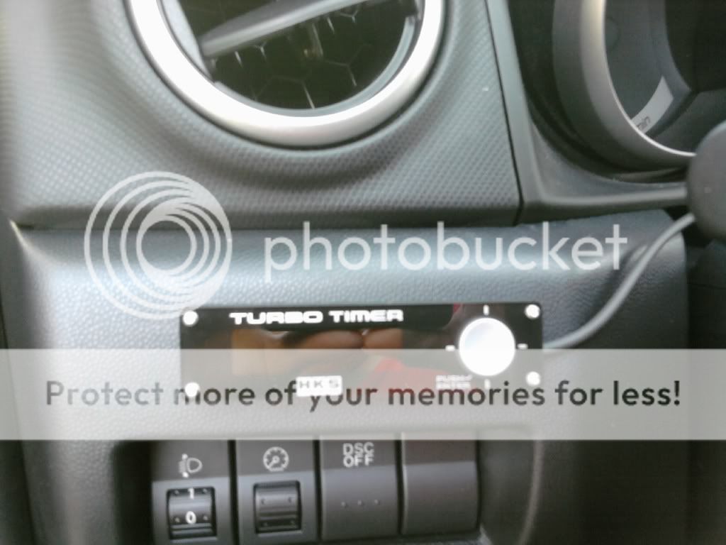
NOTE: The blue and brown cables at the bottom of the third picture go to the RPM and Speedometer wires in your car... I haven't connected mine nor do I know which wires are for the RPM/Speedo gauge, so I just tucked them back in the dash with everything.
Part 1: Make sure you’ve got a good idea of where you’ll want your final display unit to sit, so you can gauge where you’re going to put the control unit once everything is mounted… as you can see, mine is just above the dimmer and DCS switches, providing a good eye-level view (when glancing at the speedo/tac)
Part 2: With that in mind, start first and foremost by disconnecting the negative battery terminal. Don’t want any accidents. Begin the disassembly of the panels you’ll need to remove (this can basically be read side-by-side with the turbo timer write up already on here, but this is for the HKS I installed specifically for those who wanted to see how mine was done without soldering or t-connectors). Start with the MAZDASPEED sill plate, and work up, careful with the left kick-panel, that plastic tab isn’t too strong… slide a flathead into the smaller middle tab to pull out the “screw” in there, and voila, panel off. Next, locate the tab behind the hood release lever, push a flathead in there and hold it, and just yank the lever out, I just let it hang for the installation, nothing wrong with that. With that done you can locate the single phillips head screw sitting right where the lever was… take that out, and unsnap that whole entire panel from around the steering column, careful again not to break any of the tabs (no “screw” tabs this time though) carefully take it out and remove the electrical connections (headlight level, dimmer, DCS, and the OBD port). At this point you can access the Philips head screws holding the bottom half of the steering column cover in, take those out, carefully pop off the bottom cover and MAKE SURE you disconnect the wire at the right side of the column (it’s for the little red light above the ignition, it’s inconvenient if you forget, don’t wanna yank the whole thing out). With that done, we slid the top half out from the back and propped it up so we could get easier access to the wiring around there. With all of those dismantled, we moved to the center console, so we could get all the panels removed before starting anything. For the HKS units remember you MUST connect the e-brake linkage otherwise the unit just won’t function, or if it will for some reason, it’s convenient to have the e-brake linked so that you won’t ever forget to pull it.") For the center console, removal is EXTREMELY simple… you open the bottom storage area, and just pull up on the top of it to pull off the cup-holder assembly. From there, remove the shift knob and remove the shift boot and plastic base, comes right up. You can continue from here and remove the ashtray assembly or the rest of the center console entirely for ease of access to the e-brake linkage, or you can wing it like we did and do that part the hard way when you run the wire back to the steering column area. With all of this done, you’re ready to start wiring up.
For the center console, removal is EXTREMELY simple… you open the bottom storage area, and just pull up on the top of it to pull off the cup-holder assembly. From there, remove the shift knob and remove the shift boot and plastic base, comes right up. You can continue from here and remove the ashtray assembly or the rest of the center console entirely for ease of access to the e-brake linkage, or you can wing it like we did and do that part the hard way when you run the wire back to the steering column area. With all of this done, you’re ready to start wiring up.
Part 3: Starting with the e-brake area, locate the black wire with the light green stripe running its length… this is the e-brake link. What we did was carefully slice the tape and pull the plastic tube off of the wire. Then we actually cut the wire, using wire strippers to strip maybe half a centimeter on each side of the cut. Using the grey/brown extension that comes with your TT kit, take the exposed end, strip about half a centimeter from there, and just twist all 3 together with absolutely no regard for neatness, make sure all the connections meet and make sure you have them tightly wound together… we actually just kinda messed em all up and tangled em to avoid a future disconnection. Then grab your trusty (high-quality, of course) electrical tape, and tape to your heart’s content, making sure that no connection is showing. With this done, slide the wires back under the carpet piece, velcro it back up, and run the grey/brown wire through the console up to the front, now it’s your choice whether to run it THROUGH the console so you’ll never see it or run it alongside or whatever… it’s all your choice. We chose to run it through the console, it was hard to get it through the paneling we didn’t remove up front but we managed to get it done without any major problems. With that done, move your attention to the cluster of wires on the left hand side of the steering column. You will need the RED (12v constant) the YELLOW (Acc.) and the GREEN w/ YELLOW STRIPE (Ignition) wires, there will be a foam wrap and then you’ll see the tape all around the wires. Carefully cut back the tape until you have a good amount of wiring to work with. Figure out where you want to mount the actual control module of your timer (I chose the left hand brace as you can see, where I have it 3M taped to the metal AND zip-tied around) and work accordingly, threading your wires through whatever you need to get around. Cut the plastic wrap from your control module’s wires back a few inches to get adequate room to work, and in addition you’ll need to cut or push out the 3 plugs from the plugin HKS has on there (this is for their harnesses if you choose to use them, but they don’t make an MS3 specific kit) We pushed them out and ended up using the plug ends. Now remember that bottom left kick panel you took out? The one with the stupid plastic “screw” thing? Locate the black wires leading to the ground location there. That’s where you’ll want to run your own ground cable, so go ahead and do that first, just as an even more cautious precaution. You may have to spread the ends of the terminal a little bit to fit it around the bolt. With that done, we can focus our attention back on the main wiring. Make sure you take your extended grey wire and connect it to the grey wire from your control module, and your e-brake link will be done. Now take your other 3 wires and keep in mind their colors. The RED wire from the module will connect with the RED wire on the car. The BLUE wire from the module will connect with the YELLOW wire on the car. The GREEN wire from the module will connect to the GREEN w/ YELLOW STRIPE wire on the car. The way we went about wiring this was to strip about a half centimeter all the way around each wire, and we just used the existing plug connector that we kept on the module wires, bent them around and crimped them down around the stripped portions of the wires in the car. We then cross-wrapped the electrical tape, making sure to keep a tight, taught grip on the tape to ensure the connection and longevity of it. If you have a type-0 timer, this is the end of the line for your wiring. Skip down to the next part. If you have a type-1, keep reading. These next wires I haven’t actually connected myself yet, so I don't know wire colors. Locate the BLUE w/ BROWN STRIPES cable that wasn’t included in the plug portion of wires, this wire connects with your speedometer link. The BROWN w/ GREY (I believe they’re grey… can’t remember, they’re all under my dash right now haha) will connect to your Tacometer link. These are so you can use the AUTO feature on the timer, and the various other features such as your top speed, RPM level, various distance speeds, etc. Once you have found these, use a similar method that was used for the e-brake link to connect the wires. With this done, you’re ready to plug in the display, connect the battery and test out if your timer works or not. If it does, move on. If not, go back and make sure everything is connected correctly.
Part 4: Next, we’re going to mount your control, replace the panels and mount your display unit. Now, with your mounting location in mind, go ahead and figure out your own way to mount your control module. As you can see, mine is sitting in the left brace, it’s attached with 3M Molding Adhesive and then zip-tied to make sure it’s solidly mounted there and won’t be moving anytime soon. I only had smaller ties so it’s tripled haha. With that done, re-attach the steering column pieces and plug in the display unit to the control module, and then run the wire up the side of that and then off to the side, keep it alongside the column though, for your mount of the display unit. Now re-attach the rest of the panels (NOTE: when re-attaching the major panel that goes around and under the column, the one with the dimmer switch and whatnot… make sure you attach the bottom tabs first, and then move up with the attachment, otherwise you won’t attach it correctly and it’ll be off on the bottom) and make sure you don’t impede on any of the wires or the display unit’s wiring. Next is the simple part, simply use the 3M molding adhesive (or whatever you’re using) and attach it to the display unit and where you want to mount it in your car, there should be plenty of slack wiring. When you have it mounted, just shove the excess wire back into the dash, it’ll just chill behind the panels and such. And with that, you’ve just installed your very own HKS Turbo Timer, and it looks clean on top of that Hope this helps!
Here's an update from que:
"For those that have the Type I timer, I was able to hook up the RPM (Tach.) wire connection to be able to use the auto timer function. The grean wire from timer will go through the firewall. I went through the firewall where the hood release goes through. Remove the ECM connector cover. We will be using the first ECM connector if your in front of the vehicle. I soldered in my wire to pin# 2BA which is white. This is located on the front ECM connector. Pin# 2BA is the one on the left second wire if your looking at vehicle from from the front. You may have to "learn" the timer if it's off by much. Initially, I was off my 800 rpm. After I learned it, now there is a difference of about 200 rpm. Who knows which ones right. Anyways, set the timer to auto then your set. I did test the auto function this morning while going to work & it does work. It'll adjust idle times based on rpm ranges while driving. You'll see the counter adjust when you drive. The count will decrease when the rpm is under 2000. You'll figure it out."
Pictures:


Here's my finished product:
Thanks for looking and reading, this is my HKS Turbo Timer MS3 easy install write-up! This is a write-up of how I mounted my personal unit, you may alter your methods accordingly, but this is what I did.
NOTE: THERE IS A LINK TO AN EASY-TO-PRINT PDF FILE ON PAGE 2!!!
NOTE: The blue and brown cables at the bottom of the third picture go to the RPM and Speedometer wires in your car... I haven't connected mine nor do I know which wires are for the RPM/Speedo gauge, so I just tucked them back in the dash with everything.
Part 1: Make sure you’ve got a good idea of where you’ll want your final display unit to sit, so you can gauge where you’re going to put the control unit once everything is mounted… as you can see, mine is just above the dimmer and DCS switches, providing a good eye-level view (when glancing at the speedo/tac)
Part 2: With that in mind, start first and foremost by disconnecting the negative battery terminal. Don’t want any accidents. Begin the disassembly of the panels you’ll need to remove (this can basically be read side-by-side with the turbo timer write up already on here, but this is for the HKS I installed specifically for those who wanted to see how mine was done without soldering or t-connectors). Start with the MAZDASPEED sill plate, and work up, careful with the left kick-panel, that plastic tab isn’t too strong… slide a flathead into the smaller middle tab to pull out the “screw” in there, and voila, panel off. Next, locate the tab behind the hood release lever, push a flathead in there and hold it, and just yank the lever out, I just let it hang for the installation, nothing wrong with that. With that done you can locate the single phillips head screw sitting right where the lever was… take that out, and unsnap that whole entire panel from around the steering column, careful again not to break any of the tabs (no “screw” tabs this time though) carefully take it out and remove the electrical connections (headlight level, dimmer, DCS, and the OBD port). At this point you can access the Philips head screws holding the bottom half of the steering column cover in, take those out, carefully pop off the bottom cover and MAKE SURE you disconnect the wire at the right side of the column (it’s for the little red light above the ignition, it’s inconvenient if you forget, don’t wanna yank the whole thing out). With that done, we slid the top half out from the back and propped it up so we could get easier access to the wiring around there. With all of those dismantled, we moved to the center console, so we could get all the panels removed before starting anything. For the HKS units remember you MUST connect the e-brake linkage otherwise the unit just won’t function, or if it will for some reason, it’s convenient to have the e-brake linked so that you won’t ever forget to pull it.
For the center console, removal is EXTREMELY simple… you open the bottom storage area, and just pull up on the top of it to pull off the cup-holder assembly. From there, remove the shift knob and remove the shift boot and plastic base, comes right up. You can continue from here and remove the ashtray assembly or the rest of the center console entirely for ease of access to the e-brake linkage, or you can wing it like we did and do that part the hard way when you run the wire back to the steering column area. With all of this done, you’re ready to start wiring up. Part 3: Starting with the e-brake area, locate the black wire with the light green stripe running its length… this is the e-brake link. What we did was carefully slice the tape and pull the plastic tube off of the wire. Then we actually cut the wire, using wire strippers to strip maybe half a centimeter on each side of the cut. Using the grey/brown extension that comes with your TT kit, take the exposed end, strip about half a centimeter from there, and just twist all 3 together with absolutely no regard for neatness, make sure all the connections meet and make sure you have them tightly wound together… we actually just kinda messed em all up and tangled em to avoid a future disconnection. Then grab your trusty (high-quality, of course) electrical tape, and tape to your heart’s content, making sure that no connection is showing. With this done, slide the wires back under the carpet piece, velcro it back up, and run the grey/brown wire through the console up to the front, now it’s your choice whether to run it THROUGH the console so you’ll never see it or run it alongside or whatever… it’s all your choice. We chose to run it through the console, it was hard to get it through the paneling we didn’t remove up front but we managed to get it done without any major problems. With that done, move your attention to the cluster of wires on the left hand side of the steering column. You will need the RED (12v constant) the YELLOW (Acc.) and the GREEN w/ YELLOW STRIPE (Ignition) wires, there will be a foam wrap and then you’ll see the tape all around the wires. Carefully cut back the tape until you have a good amount of wiring to work with. Figure out where you want to mount the actual control module of your timer (I chose the left hand brace as you can see, where I have it 3M taped to the metal AND zip-tied around) and work accordingly, threading your wires through whatever you need to get around. Cut the plastic wrap from your control module’s wires back a few inches to get adequate room to work, and in addition you’ll need to cut or push out the 3 plugs from the plugin HKS has on there (this is for their harnesses if you choose to use them, but they don’t make an MS3 specific kit) We pushed them out and ended up using the plug ends. Now remember that bottom left kick panel you took out? The one with the stupid plastic “screw” thing? Locate the black wires leading to the ground location there. That’s where you’ll want to run your own ground cable, so go ahead and do that first, just as an even more cautious precaution. You may have to spread the ends of the terminal a little bit to fit it around the bolt. With that done, we can focus our attention back on the main wiring. Make sure you take your extended grey wire and connect it to the grey wire from your control module, and your e-brake link will be done. Now take your other 3 wires and keep in mind their colors. The RED wire from the module will connect with the RED wire on the car. The BLUE wire from the module will connect with the YELLOW wire on the car. The GREEN wire from the module will connect to the GREEN w/ YELLOW STRIPE wire on the car. The way we went about wiring this was to strip about a half centimeter all the way around each wire, and we just used the existing plug connector that we kept on the module wires, bent them around and crimped them down around the stripped portions of the wires in the car. We then cross-wrapped the electrical tape, making sure to keep a tight, taught grip on the tape to ensure the connection and longevity of it. If you have a type-0 timer, this is the end of the line for your wiring. Skip down to the next part. If you have a type-1, keep reading. These next wires I haven’t actually connected myself yet, so I don't know wire colors. Locate the BLUE w/ BROWN STRIPES cable that wasn’t included in the plug portion of wires, this wire connects with your speedometer link. The BROWN w/ GREY (I believe they’re grey… can’t remember, they’re all under my dash right now haha) will connect to your Tacometer link. These are so you can use the AUTO feature on the timer, and the various other features such as your top speed, RPM level, various distance speeds, etc. Once you have found these, use a similar method that was used for the e-brake link to connect the wires. With this done, you’re ready to plug in the display, connect the battery and test out if your timer works or not. If it does, move on. If not, go back and make sure everything is connected correctly.
Part 4: Next, we’re going to mount your control, replace the panels and mount your display unit. Now, with your mounting location in mind, go ahead and figure out your own way to mount your control module. As you can see, mine is sitting in the left brace, it’s attached with 3M Molding Adhesive and then zip-tied to make sure it’s solidly mounted there and won’t be moving anytime soon. I only had smaller ties so it’s tripled haha. With that done, re-attach the steering column pieces and plug in the display unit to the control module, and then run the wire up the side of that and then off to the side, keep it alongside the column though, for your mount of the display unit. Now re-attach the rest of the panels (NOTE: when re-attaching the major panel that goes around and under the column, the one with the dimmer switch and whatnot… make sure you attach the bottom tabs first, and then move up with the attachment, otherwise you won’t attach it correctly and it’ll be off on the bottom) and make sure you don’t impede on any of the wires or the display unit’s wiring. Next is the simple part, simply use the 3M molding adhesive (or whatever you’re using) and attach it to the display unit and where you want to mount it in your car, there should be plenty of slack wiring. When you have it mounted, just shove the excess wire back into the dash, it’ll just chill behind the panels and such. And with that, you’ve just installed your very own HKS Turbo Timer, and it looks clean on top of that
Hope this helps!Here's an update from que:
"For those that have the Type I timer, I was able to hook up the RPM (Tach.) wire connection to be able to use the auto timer function. The grean wire from timer will go through the firewall. I went through the firewall where the hood release goes through. Remove the ECM connector cover. We will be using the first ECM connector if your in front of the vehicle. I soldered in my wire to pin# 2BA which is white. This is located on the front ECM connector. Pin# 2BA is the one on the left second wire if your looking at vehicle from from the front. You may have to "learn" the timer if it's off by much. Initially, I was off my 800 rpm. After I learned it, now there is a difference of about 200 rpm. Who knows which ones right. Anyways, set the timer to auto then your set. I did test the auto function this morning while going to work & it does work. It'll adjust idle times based on rpm ranges while driving. You'll see the counter adjust when you drive. The count will decrease when the rpm is under 2000. You'll figure it out."
Pictures:
Here's my finished product:
Last edited: