The following install was done by myself without any help from friends, if you do this alone..... on average it should take between 30 minutes to 60 minutes for install, provided you don't run into any problems:
*PLEASE KEEP IN MIND THIS SETUP IS ON A SPEED6, IT WILL WORK WITH A MAZDA6 AS I HAVE PERFORMED THE SAME SETUP ON MY GIRL'S MAZDA6s HATCH, HOWEVER THE COLORS OF THE WIRES ON THE FACTORY BOSE ARE DIFFERENT COLORED FOR SOME OF THE YEARS, MY GF'S 2005 HATCH HAD THE SAME COLORS AS I DID IN THE SPEED*
and yes I know I need to clean up the cables in the back... just haven't had much time/been lazy, lol. It works, and that's all I care about. Oh and I've been running this setup since I got the car in April 2007, haven't had a single hiccup with it, and neither has my GF in her car.
Amp 12volt cable connected to the battery terminal
I decided to just zip-tie the 12volt fuse to a cable, instead of drilling it to a surface, this allows me to just easily unscrew it should the fuse inside pop for whatever reason, makes replacing it easier.
I didn't want to drill a hole in my firewall like some people do, so I fed the cable through the grommet, it helps if you use a lead string to feed it through, this took me a good 4 or 5 minutes to make sure i got it through

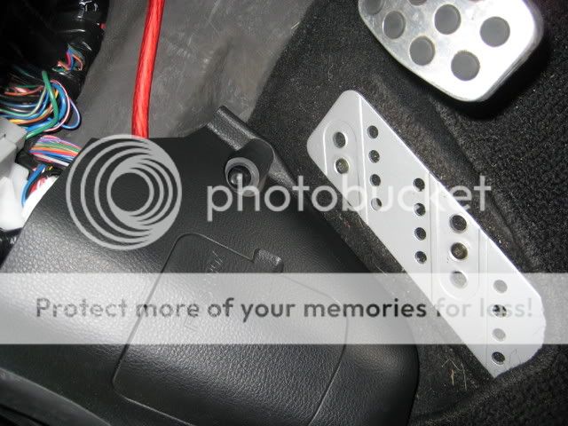
view of 12volt fed through grommet from inside of car, it is in fact, easier to push the 12volt power cable through the inside of the car than going through the outside, unless you remove your battery.... if you push it through here and you're doing the install alone, you may need a wire coat hanger to pull the cable UP to you a bit, since it tends to go downwards from the grommet
ran it behind the fuse box to keep it out of the way....
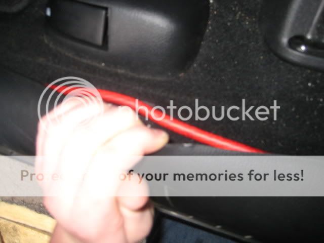
Popped out the door lined plastic paneling to put the cable under, all along the driverside door.
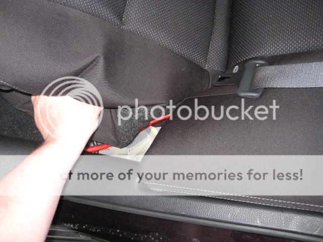
fed it up and under through my seat to go through the back...
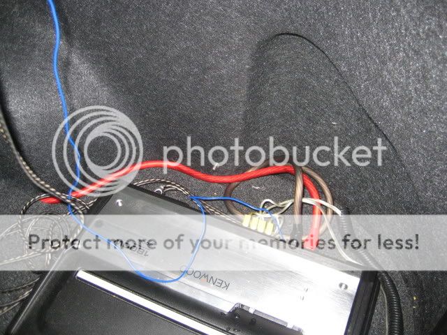
fed it up through the back and attached it to the amp
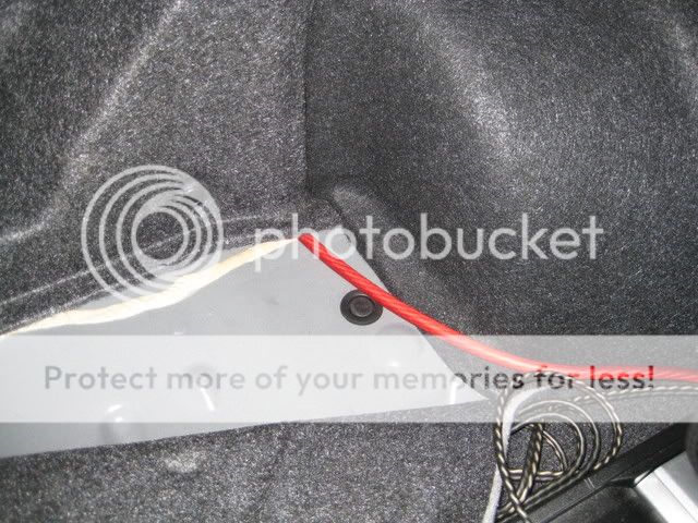
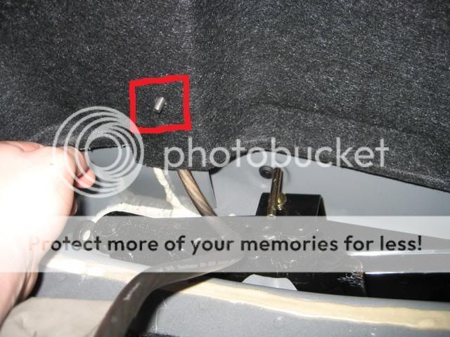
Removed the little plastic pop cap (red square area) that holds the liner to the car and inserted a bolt from behind and used this to "ground" the amp, I also used an M6 (6mm metric) bolt and nut to make sure the ground was nice and tight against the car, this is one of the best places to ground the amp because of it's unpainted surface.
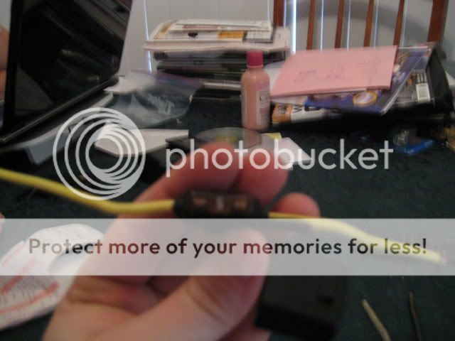
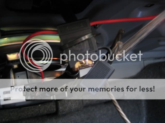
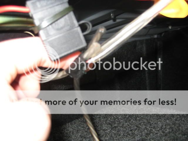
The remote ACC amp turn on wire.... i connected it to a fuse loop cable... before tapping into the BOSE amp turn on, this will save your electrical system in the event of a surge from either your car or the aftermarket amp, the fuse will pop and disconnect between the 2, I picked this one up at ACE hardware for less than 2 dollars. If the fuse does pop you can put another one in, and if that pops too then that saves your system and tells you that you have a spike going on somewhere.
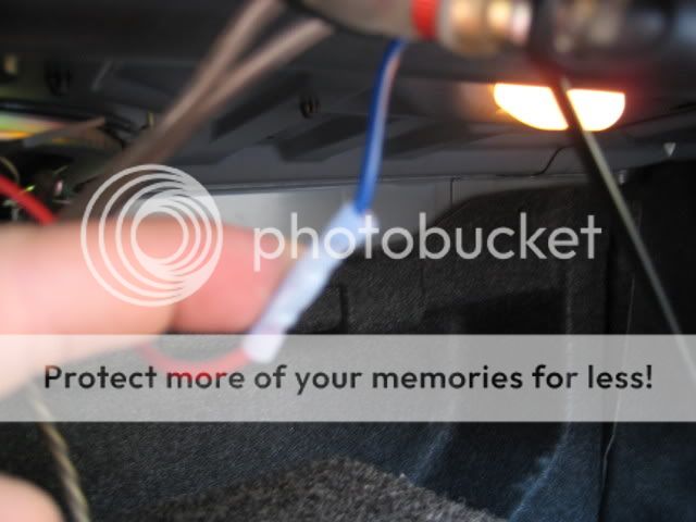
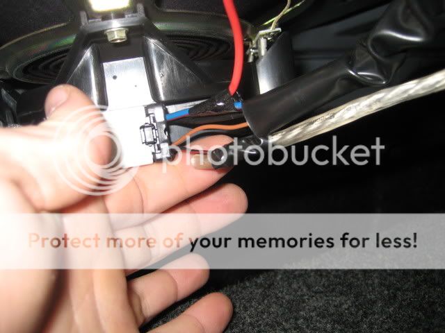
wired the fuse loop cable to the BLUE W/RED STRIP factory ACC (this is used for the aftermarket amp's ACC remote turnon cable... to turn the amp on when your stereo is on.)
ok here's where the tricky part comes in, and I'll show some better pictures on how it should look when you do it....
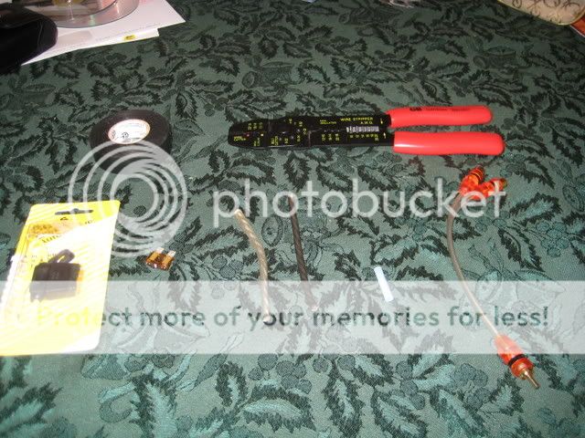
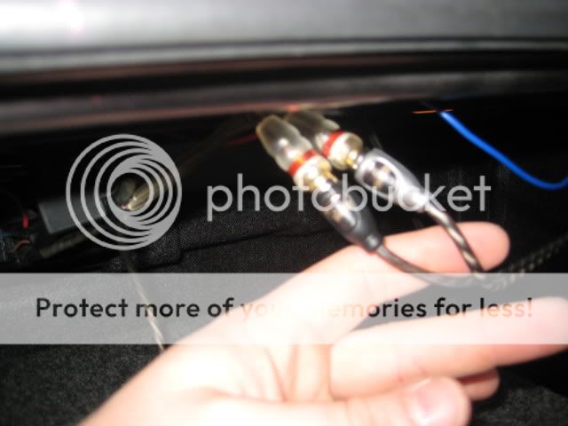
you basically need a small 1 male to 2 female RCA cable (learn how to make one here) (the clear plastic one in the pic with the other end appearing cut off)... this is what allows you to plug in the RCA cable from your aftermarket amplifier from your RIGHT IN and your LEFT IN(doesn't matter which you plug into which)
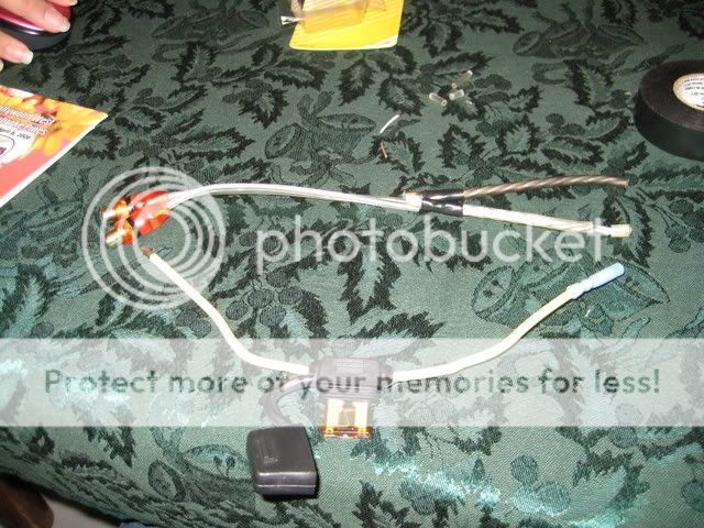
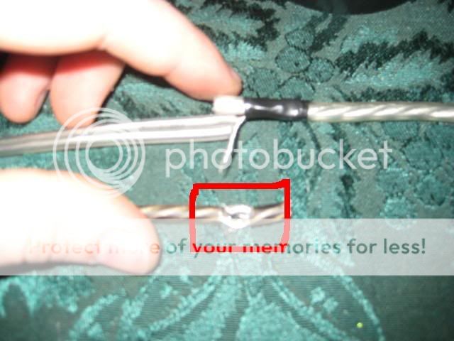
you have to cut off the male end on the RCA and then strip the rubber insulation.... you then have to seperate the silver shielding from the copper core, this is what gives you the negative and positive (copper core will be positive) you take the copper core from both cables and twist them together, and the silver shielding from both cables you twist together
you will then need to get 2 seperate pieces of audio cable.... i used white and black to tell the difference between the positive (white) and the negative/ground (black),
you splice the copper cables you twisted into the white positive audio cable, and the silver shielding to the baclk ground cable.
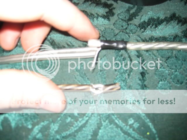
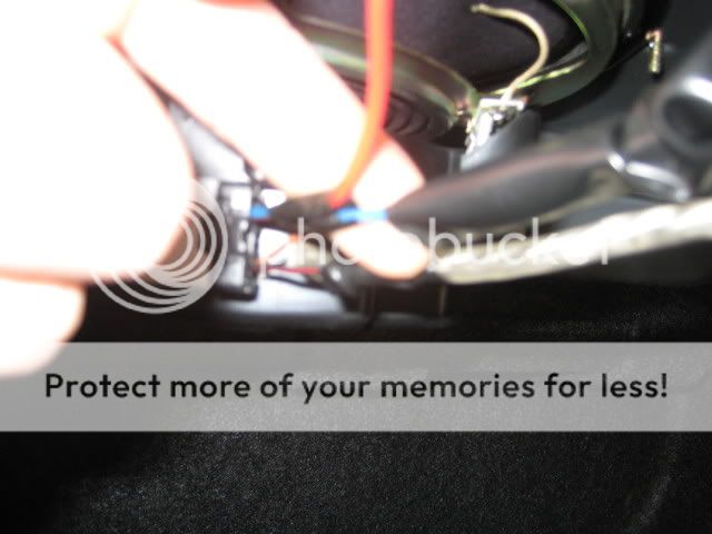
then you take the positive white audio cable, strip the tip to expose it's copper core and you have to splice into the BOSE audio signal cable (BLACK WITH RED STRIPE), you only need to splice the POSITIVE speaker wire into the audio signal cable, the black with red stripe. The NEGATIVE speaker wire does not need to be spliced into anything, and can sit there freely. it only needs one end spliced into your RCA splitter, the other end does not need to spliced into the factory wires, it is a negative and doesn't retain a signal from any of the wires on your BOSE sub.
after that you're prettu much done... and yes I know i need to clean up the cables a little, I ended up buying a 10 foot twisted pair RCA cable for the amp and it was longer than I thought I would need.
I'm also going to make an enclosure, where i remove the back paneling and expose the X cross/brace bars, and building an enclosure to support the sub woofers between those, so they will fill up that area and cover it back up, but my subs will appear "flush" with the back of the car, and it will also give me back my trunk space. and I'll have mounted/drilled the amp to the roof of the trunk, to completely get all the wires out of the way.

and incase anyone is wondering.... I'm running a kenwood 1800w amp with 2 kenwood 1000w 12" subs. for those of you who haven't installed their subs, or screwed them into a box, I would recommend getting a perfect square box, why? More airspace per cubic foot inside the box for the subwoofer.
*PLEASE KEEP IN MIND THIS SETUP IS ON A SPEED6, IT WILL WORK WITH A MAZDA6 AS I HAVE PERFORMED THE SAME SETUP ON MY GIRL'S MAZDA6s HATCH, HOWEVER THE COLORS OF THE WIRES ON THE FACTORY BOSE ARE DIFFERENT COLORED FOR SOME OF THE YEARS, MY GF'S 2005 HATCH HAD THE SAME COLORS AS I DID IN THE SPEED*
and yes I know I need to clean up the cables in the back... just haven't had much time/been lazy, lol. It works, and that's all I care about. Oh and I've been running this setup since I got the car in April 2007, haven't had a single hiccup with it, and neither has my GF in her car.
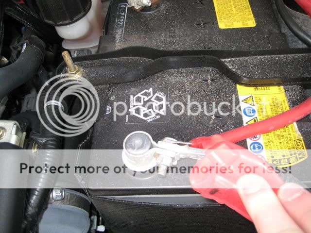
Amp 12volt cable connected to the battery terminal
I decided to just zip-tie the 12volt fuse to a cable, instead of drilling it to a surface, this allows me to just easily unscrew it should the fuse inside pop for whatever reason, makes replacing it easier.
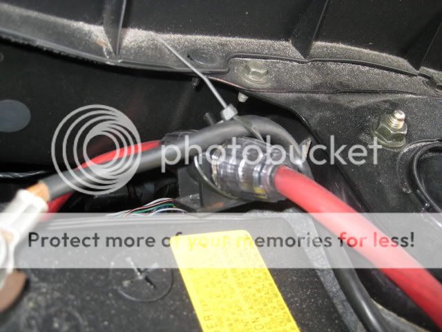
I didn't want to drill a hole in my firewall like some people do, so I fed the cable through the grommet, it helps if you use a lead string to feed it through, this took me a good 4 or 5 minutes to make sure i got it through
view of 12volt fed through grommet from inside of car, it is in fact, easier to push the 12volt power cable through the inside of the car than going through the outside, unless you remove your battery.... if you push it through here and you're doing the install alone, you may need a wire coat hanger to pull the cable UP to you a bit, since it tends to go downwards from the grommet
ran it behind the fuse box to keep it out of the way....
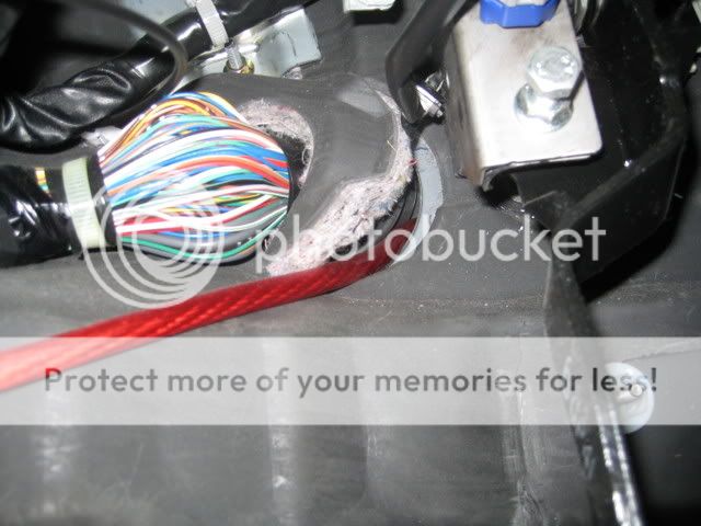
Popped out the door lined plastic paneling to put the cable under, all along the driverside door.
fed it up and under through my seat to go through the back...
fed it up through the back and attached it to the amp
Removed the little plastic pop cap (red square area) that holds the liner to the car and inserted a bolt from behind and used this to "ground" the amp, I also used an M6 (6mm metric) bolt and nut to make sure the ground was nice and tight against the car, this is one of the best places to ground the amp because of it's unpainted surface.
The remote ACC amp turn on wire.... i connected it to a fuse loop cable... before tapping into the BOSE amp turn on, this will save your electrical system in the event of a surge from either your car or the aftermarket amp, the fuse will pop and disconnect between the 2, I picked this one up at ACE hardware for less than 2 dollars. If the fuse does pop you can put another one in, and if that pops too then that saves your system and tells you that you have a spike going on somewhere.
wired the fuse loop cable to the BLUE W/RED STRIP factory ACC (this is used for the aftermarket amp's ACC remote turnon cable... to turn the amp on when your stereo is on.)
ok here's where the tricky part comes in, and I'll show some better pictures on how it should look when you do it....
you basically need a small 1 male to 2 female RCA cable (learn how to make one here) (the clear plastic one in the pic with the other end appearing cut off)... this is what allows you to plug in the RCA cable from your aftermarket amplifier from your RIGHT IN and your LEFT IN(doesn't matter which you plug into which)
you have to cut off the male end on the RCA and then strip the rubber insulation.... you then have to seperate the silver shielding from the copper core, this is what gives you the negative and positive (copper core will be positive) you take the copper core from both cables and twist them together, and the silver shielding from both cables you twist together
you will then need to get 2 seperate pieces of audio cable.... i used white and black to tell the difference between the positive (white) and the negative/ground (black),
you splice the copper cables you twisted into the white positive audio cable, and the silver shielding to the baclk ground cable.
then you take the positive white audio cable, strip the tip to expose it's copper core and you have to splice into the BOSE audio signal cable (BLACK WITH RED STRIPE), you only need to splice the POSITIVE speaker wire into the audio signal cable, the black with red stripe. The NEGATIVE speaker wire does not need to be spliced into anything, and can sit there freely. it only needs one end spliced into your RCA splitter, the other end does not need to spliced into the factory wires, it is a negative and doesn't retain a signal from any of the wires on your BOSE sub.
after that you're prettu much done... and yes I know i need to clean up the cables a little, I ended up buying a 10 foot twisted pair RCA cable for the amp and it was longer than I thought I would need.
I'm also going to make an enclosure, where i remove the back paneling and expose the X cross/brace bars, and building an enclosure to support the sub woofers between those, so they will fill up that area and cover it back up, but my subs will appear "flush" with the back of the car, and it will also give me back my trunk space. and I'll have mounted/drilled the amp to the roof of the trunk, to completely get all the wires out of the way.
and incase anyone is wondering.... I'm running a kenwood 1800w amp with 2 kenwood 1000w 12" subs. for those of you who haven't installed their subs, or screwed them into a box, I would recommend getting a perfect square box, why? More airspace per cubic foot inside the box for the subwoofer.
Last edited:
")