floriske.nl
Member
- :
- Mazda 5 exclusive sport 2006
Mazda 5 - 2006 multiple (head unit) questions
I bought myself a DVD/NAV Windows CE head unit and 2 din (178x100mm) dash frame for my 2006 Mazda 5.
I'm working on a wiring harness for it. For this I bought a fully wired Mazda connector and some ISO connectors (to make it usable on other units in the future as well).
The problem is that I found multiple different pinout schematics for the Mazda connector:
View attachment Mazda 5 Connector Pinouts.xls
As you can see in the above Excel sheet the 3 schematics I found differ on multiple pins. Can somebody confirm which of the 3 is correct?
---
Furthermore I'm having doubts about the steering wheel controls. As far as I could find the car uses resistance based controls which I can directly connect to the Head unit which has a "learning" function for each button.
The head unit has 2 wires "Key 1" and "Key 2". These aren't "signal" and "gnd" for a single panel, but can be used for 2 diffent button panels. Since I couldn't figure out how to connect these I had a look at the PAC SWI RC user manual since that had a wiring advice for the 2006 Mazda 5. That manual stated that one wire of the panel goes to the unit's steering wheel control input and the other to the chassis ground.
Based on this I figured I need to do the same on my head unit: one wire on Key 1 and the other connected to chassis ground. Can somebody confirm this is correct?
---
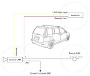
Last but not least I was wondering where you guys placed the GPS antenna and what would be the best spot to connect the "Reverse" wire of the head unit to? Is there a spot in the front/dashboard to connect this wire to (e.g. near the shifter) or should I connect it to the reverse light +.
Last edited:

