mazdaspeeeeed
Member
- :
- MSP 2003.5
cluster install is complete pending a few pictures... ac controls coming soon!


No longer doing AMM. They want $13 per month (they really should list that on the sign up page) and I dont see it being worth it unless there are enough ppl who would be interested... lets say 5 people
In this How To I used a MSP gauge cluster. The 2001+ DX/LX and the 99-00 protege have a green film on the gauges but the same method can be applied. Now let's get busy!
Tools Needed: Flat head, phillips head, small set of phillips heads, scissors, marker, olfa blade, needle nose pliers, 12v power supply, tin snips, hot glue, stapler, wire strippers, and lots of patience...
Things to Buy:
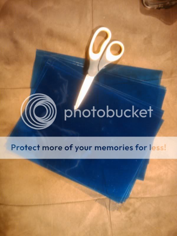
-Blue Transparency
-https://www.ebay.com (commissions earned)
-https://www.ebay.com (commissions earned)
-https://www.ebay.com (commissions earned)
-18g Wire Spool
-Wire Connectors
-100-220 grit sandpaper
Total Time (cluster): 6-7 hours
Total Time (AC): 1-2 hours
Total Cost: $40 (blue LEDs, white LEDs, red LEDs, sandpaper, transparencies, wires and connectors)
How To: Blue Gauge Cluster
Chapter 1 - Remove Gauge Cluster
Time: 5 min
1) Set steering wheel to the lowest position
2) Unscrew 2 small screws on the black gauge surround
3) Pull off gauge surround and set it aside
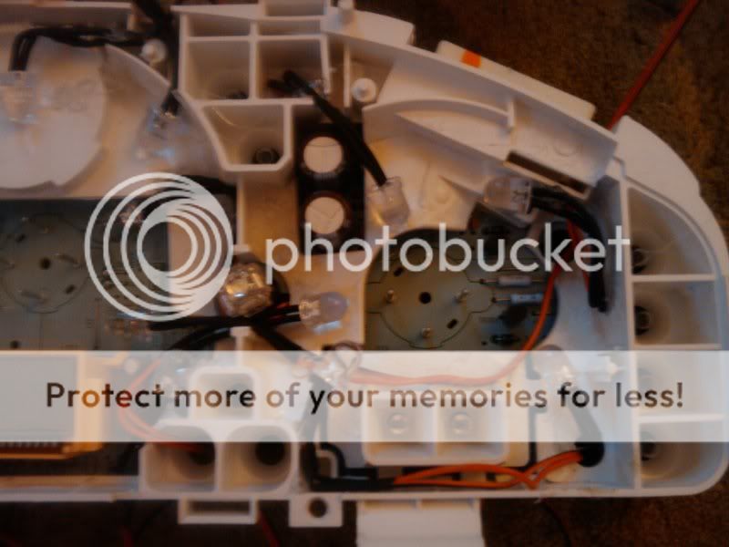
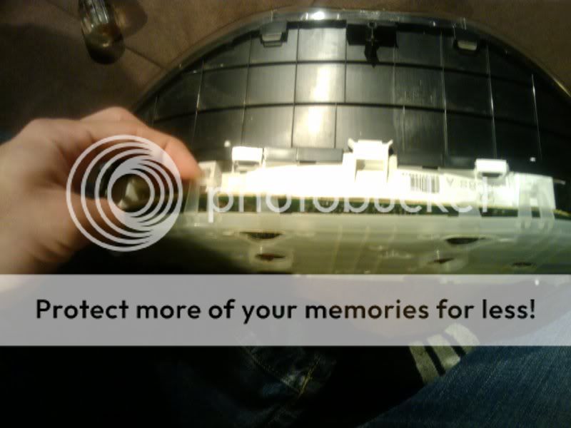
4) Unscrew all of the screws holding the gauge cluster in place
5) Place a towel down on the steering column to avoid scratching it
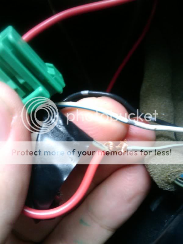
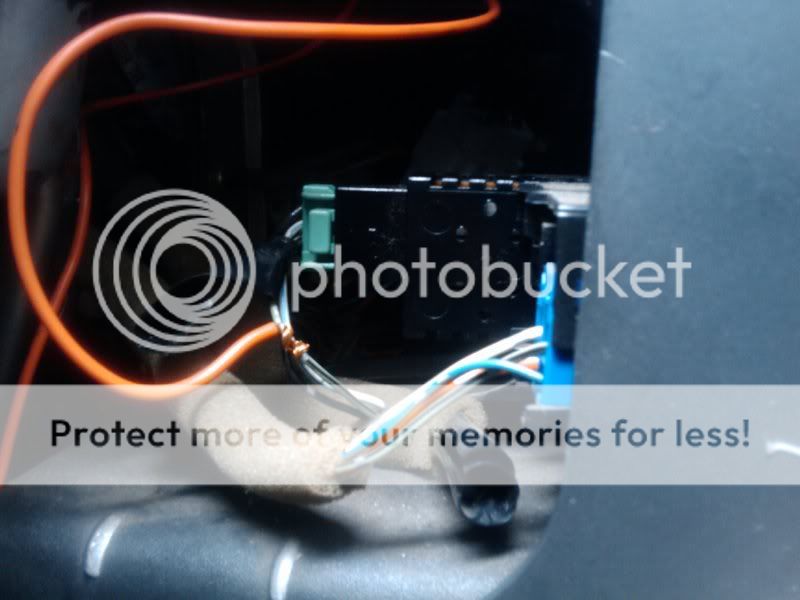
6) Pull out the gauge cluster from the top first until you can reach/see the connectors.
7) Disconnect all of the connectors from the back.
8) Pull out the gauge cluster being careful not to scratch anything
9) Take cluster inside to a comfortable place to work
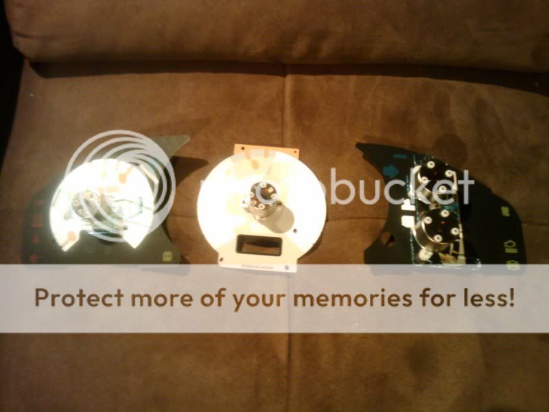
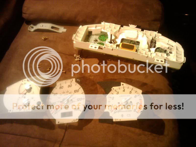
Chapter 2 - Gauge Disassembly
Time: 1hr 30min

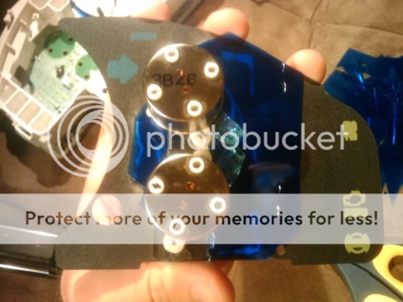
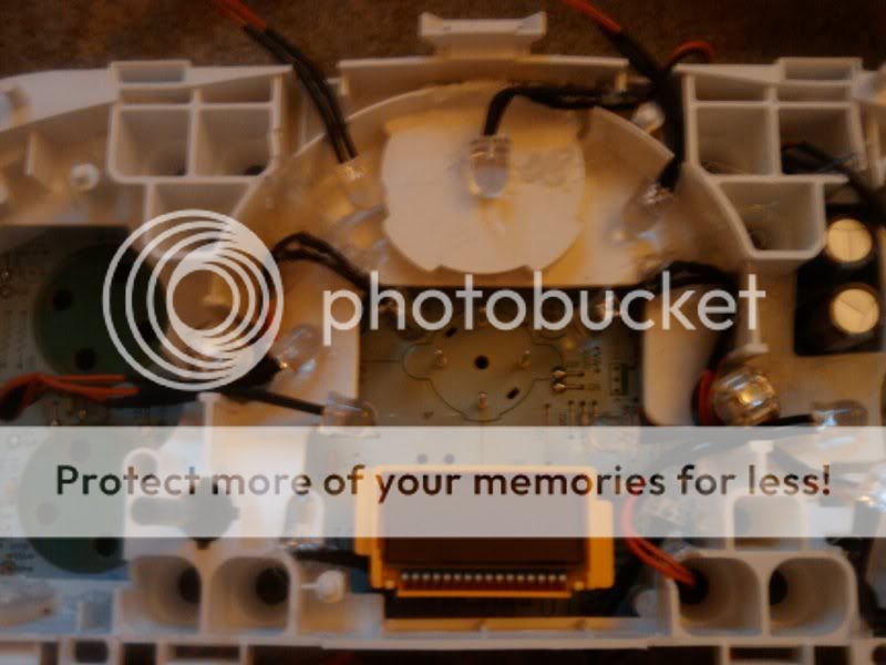
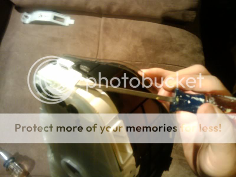
1) remove the metal mounting bracket
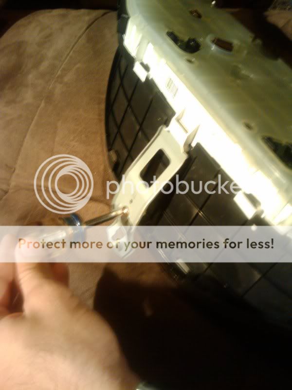
2) unscrew the 4 gold screws on the back of the gauge assembly that hold on the plastic cover
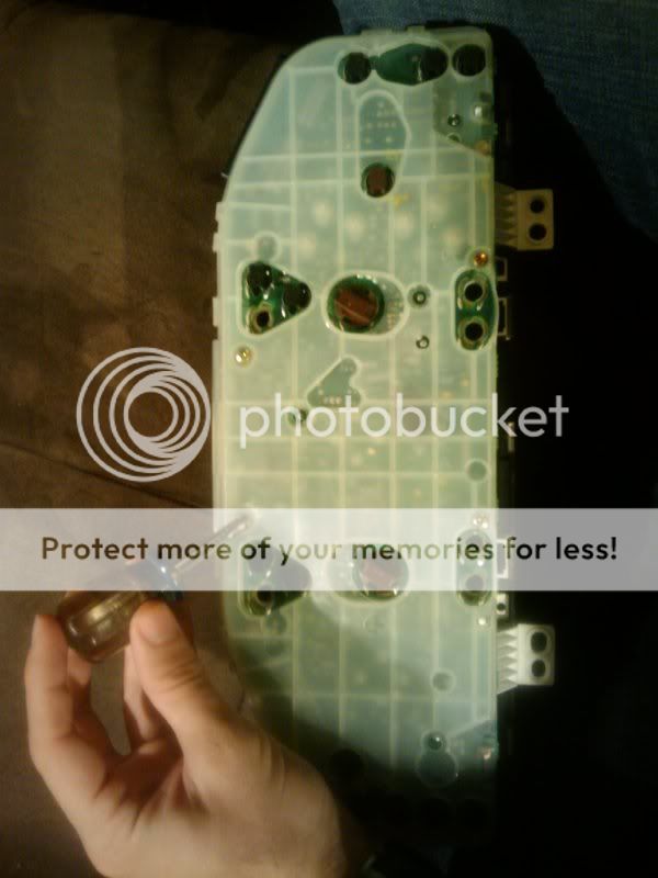
3) remove plastic cover by unsnapping the 4 tabs.
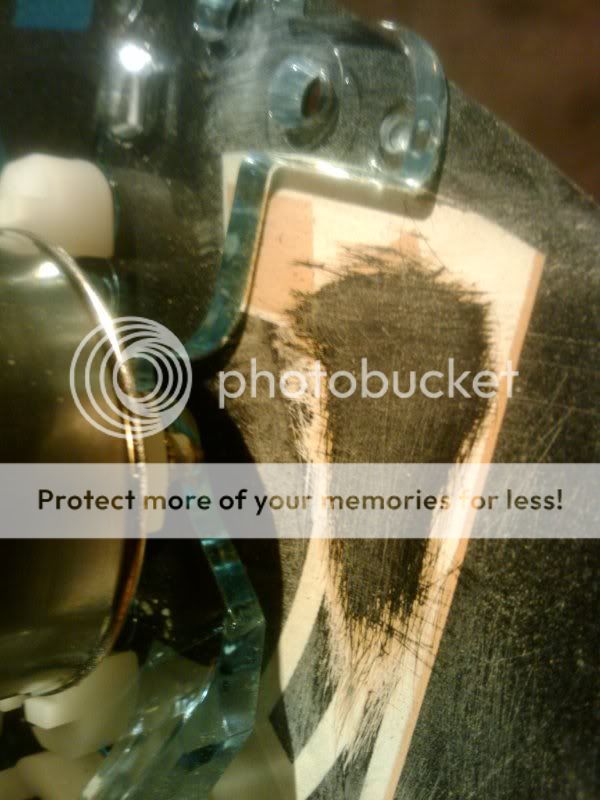
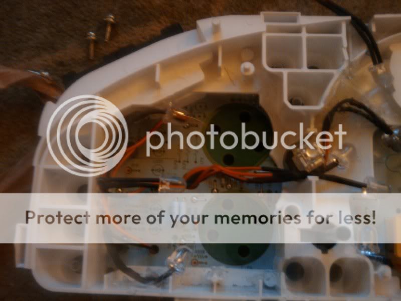
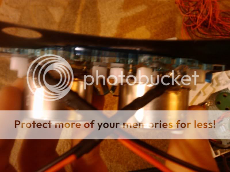
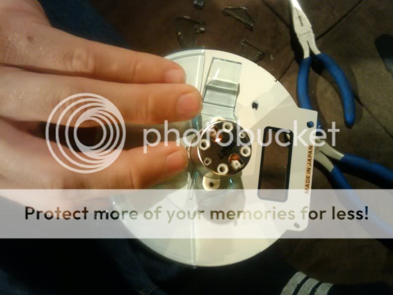
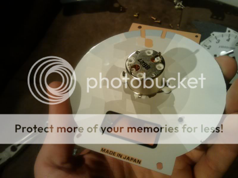
4) unscrew the gas/temp gauges (6 silver screws) on the right side of the circuit board as shown
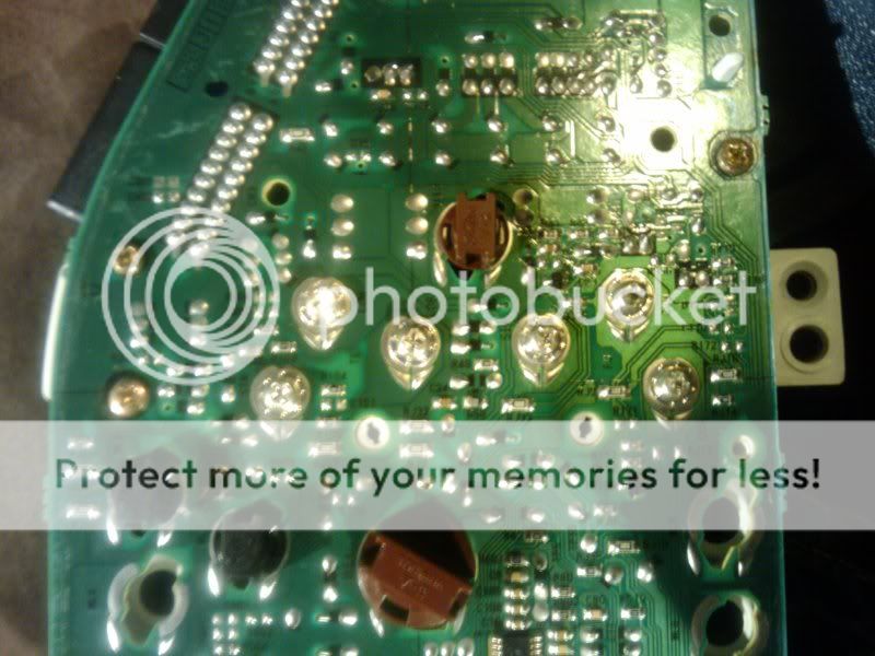
5) pry back the 2 silver tabs for the speedo using a flathead. (try not to scratch the circuit board)

6) pry back the 2 silver tabs for the tach using a flathead.

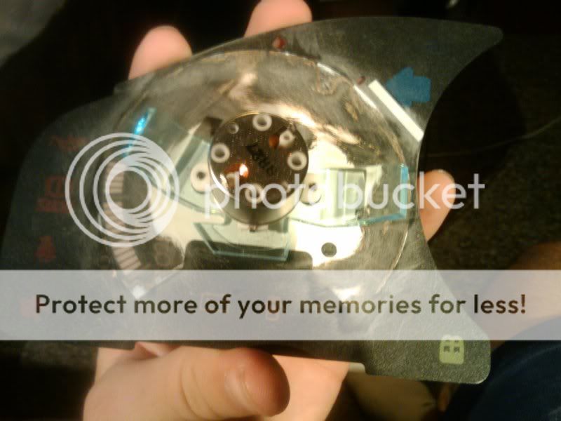
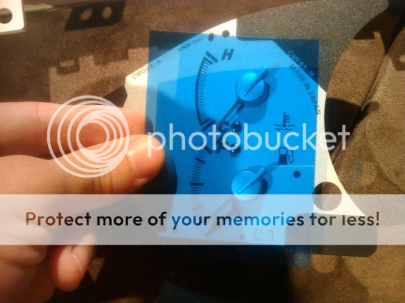
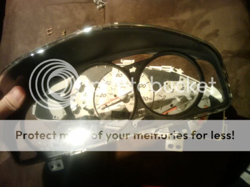
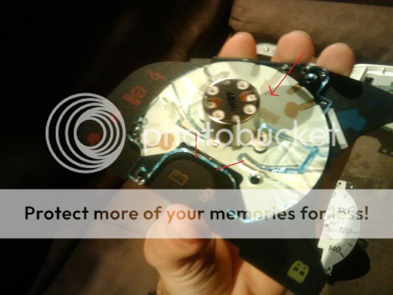
7) unclip all the black tabs holding on the black gauge surround. (there is no reason to remove the clear plastic on the front as this comes of with the gauge surround. Use a flathead screwdriver and gently push each tab through. Once you get most of them out you should be able to just pull it off.
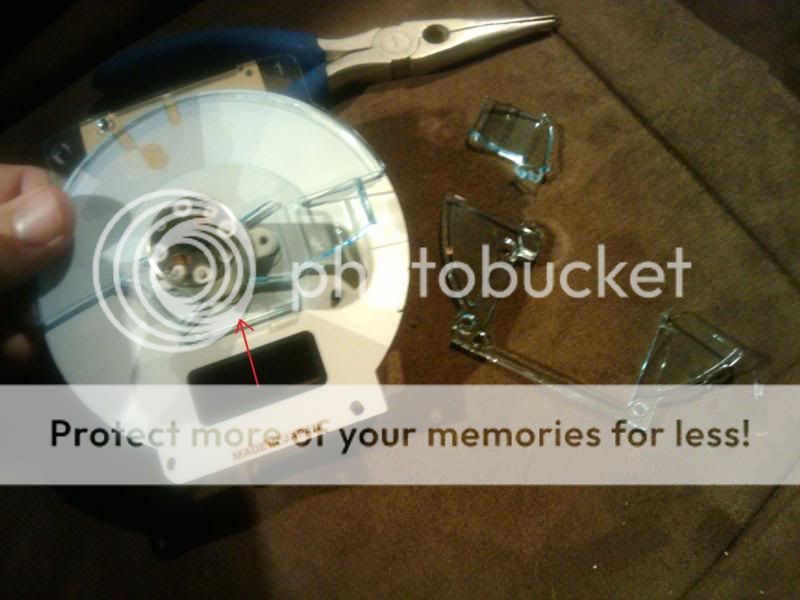
8) pull out all three gauges. The gas/temp will come out easy. The speedo and tach you may have to flip over and push the silver tabs through the circuit board.
Be very careful while removing these. Needles will break.
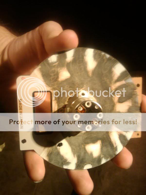
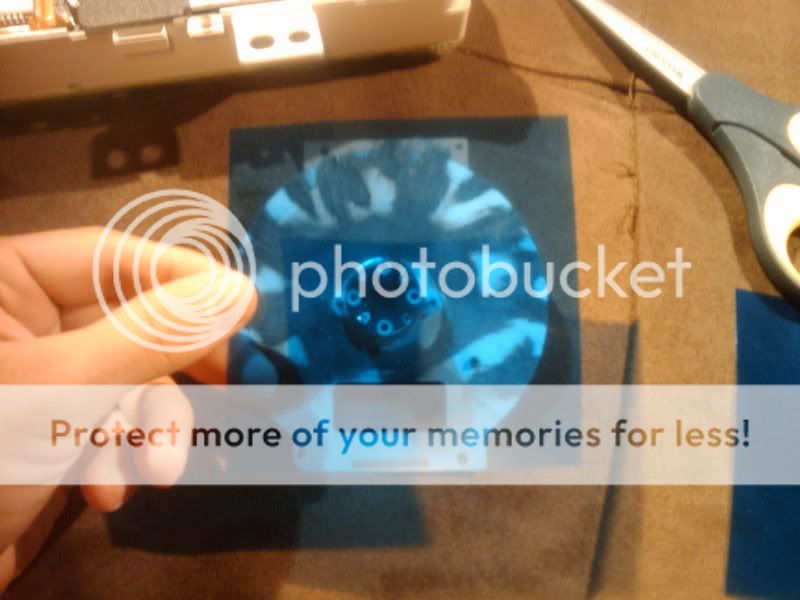
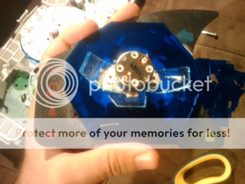
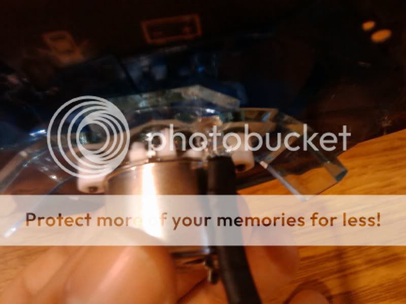
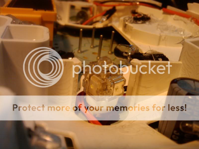
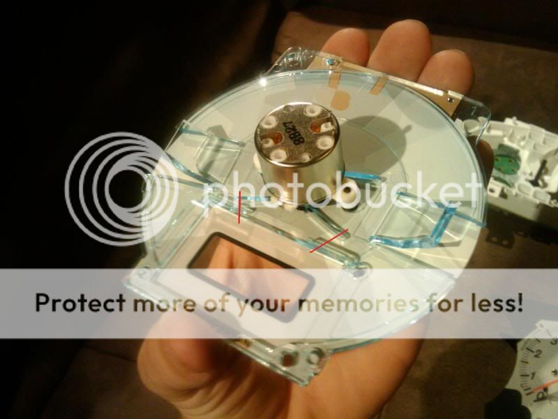
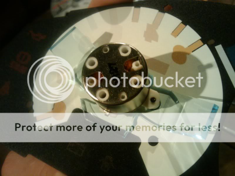
9) each gauge has a clear plastic on the back side as shown we will need to remove this in order to sand. If you take off the needles it is very hard to recalibrate, plus needles break. But if you feel comfortable go ahead and remove the needles using 2 spoons. However this tutorial is not following that process.
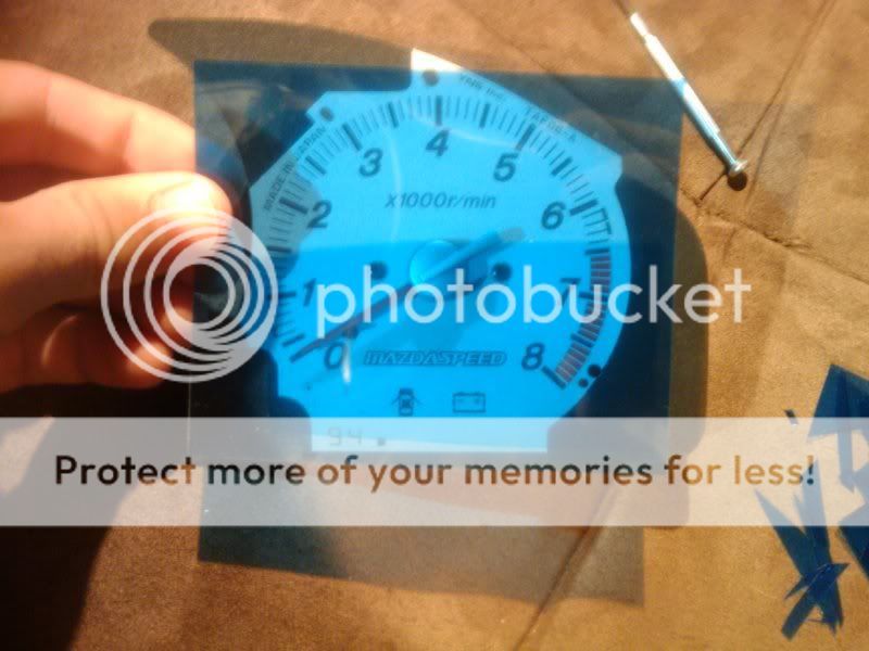
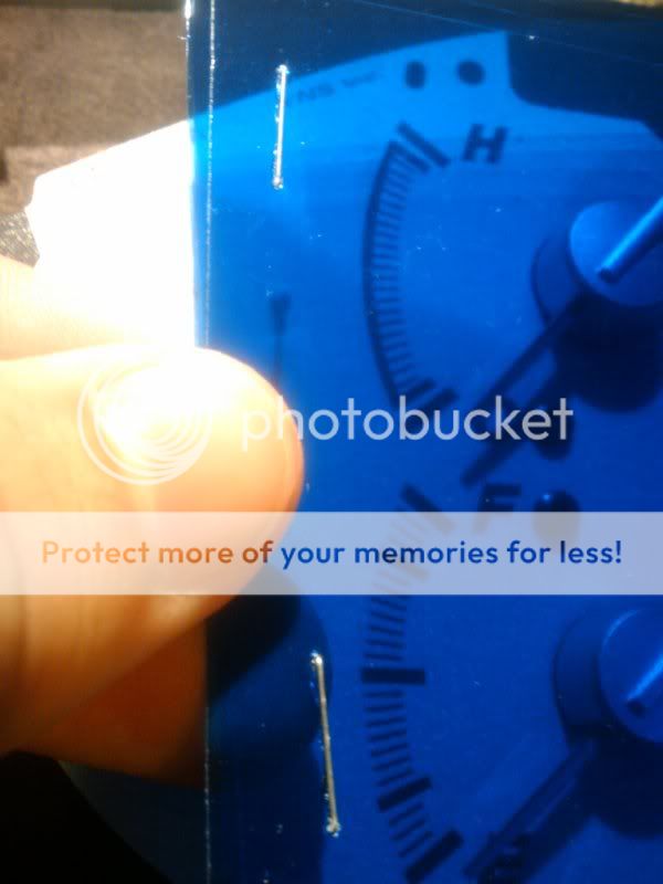
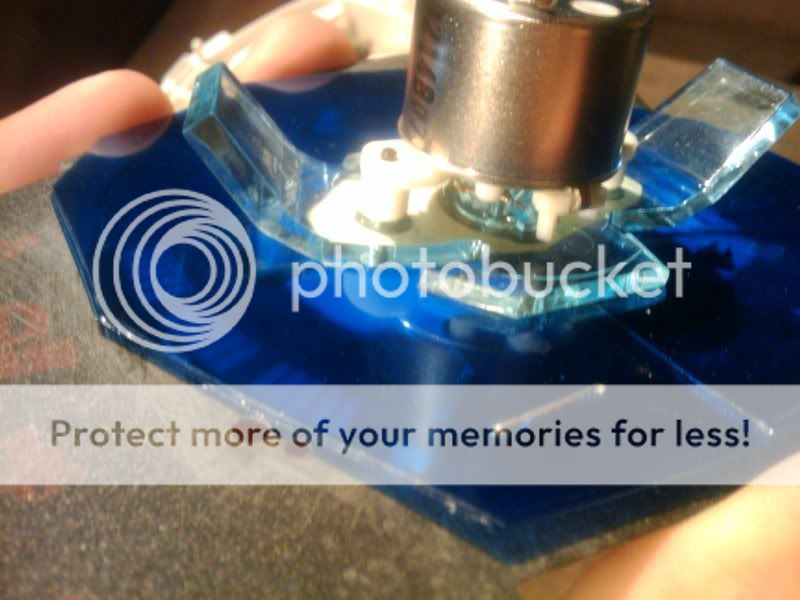
10) On the speedo gauge using a pair of needle nose pliers and tin snips very very carefully cut the plastic at these first 2 locations.
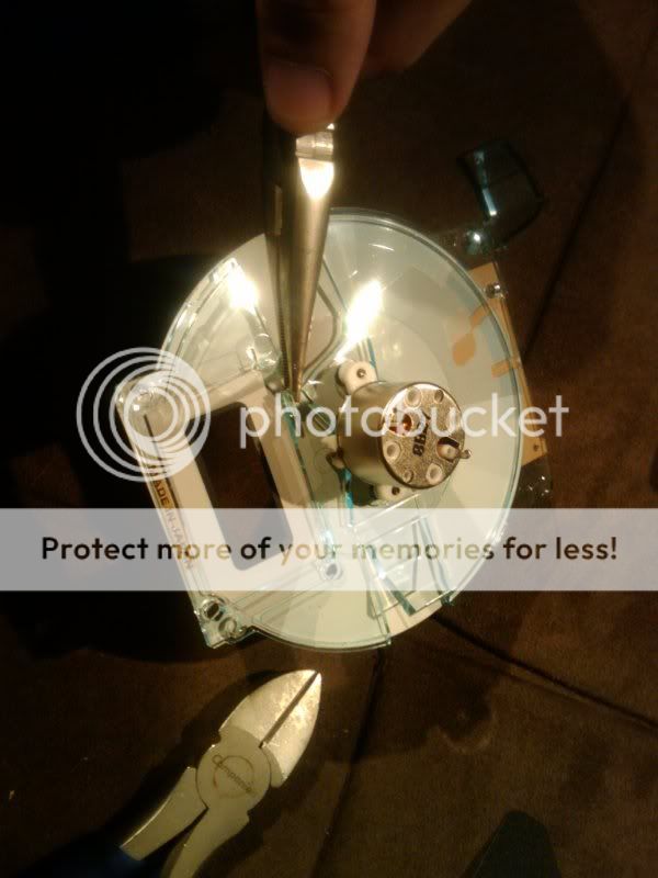
11) Hold the gauge in your hand as shown to keep pressure off the needle.
12) Then using the needle nose pliers snap this part of the plastic off. (it took me a good 30 min of slowly breaking pieces off before I finally got it) we are trying to get the plastic to a point where we can just slide it out.
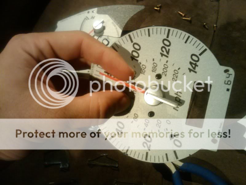
13) Once you have a clear path for the plastic to slide off flip the gauge over and unscrew the 2 small black screws
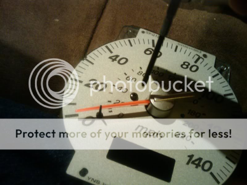
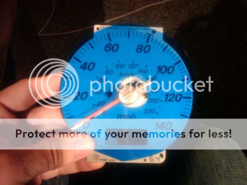
14) Slide off the clear plastic
15) Screw back in the 2 black screws to keep the needle from bouncing around
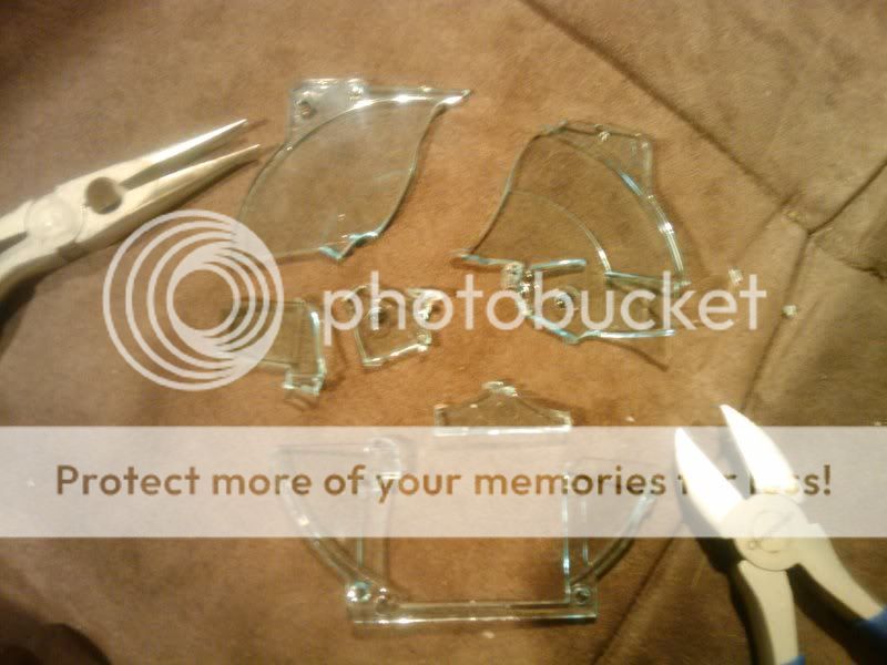
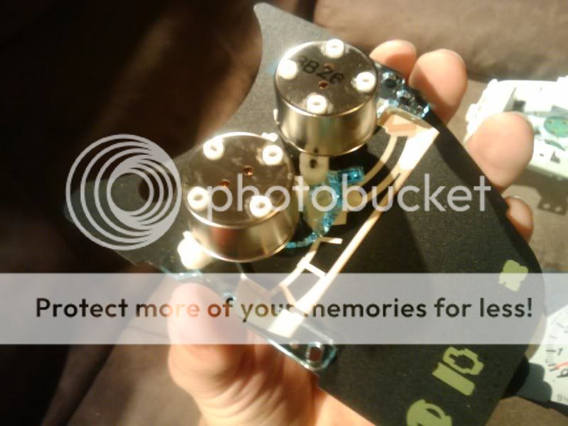
16) The other 2 gauges are a lot easier. Starting with the tach cut the plastic in the 2 bottom places marked and snap the top piece off with the pliers.
Warning: plastic will shoot out very fast so watch your eyes.
17) The gas/temp gauges are the most sensitive so you can either not break any pieces off or snap off the 2 pieces at the top and bottom that cover the H and E.
18) Now you are ready for sanding!


No longer doing AMM. They want $13 per month (they really should list that on the sign up page) and I dont see it being worth it unless there are enough ppl who would be interested... lets say 5 people
In this How To I used a MSP gauge cluster. The 2001+ DX/LX and the 99-00 protege have a green film on the gauges but the same method can be applied. Now let's get busy!
Tools Needed: Flat head, phillips head, small set of phillips heads, scissors, marker, olfa blade, needle nose pliers, 12v power supply, tin snips, hot glue, stapler, wire strippers, and lots of patience...
Things to Buy:
-Blue Transparency
-https://www.ebay.com (commissions earned)
-https://www.ebay.com (commissions earned)
-https://www.ebay.com (commissions earned)
-18g Wire Spool
-Wire Connectors
-100-220 grit sandpaper
Total Time (cluster): 6-7 hours
Total Time (AC): 1-2 hours
Total Cost: $40 (blue LEDs, white LEDs, red LEDs, sandpaper, transparencies, wires and connectors)
How To: Blue Gauge Cluster
Chapter 1 - Remove Gauge Cluster
Time: 5 min
1) Set steering wheel to the lowest position
2) Unscrew 2 small screws on the black gauge surround
3) Pull off gauge surround and set it aside
4) Unscrew all of the screws holding the gauge cluster in place
5) Place a towel down on the steering column to avoid scratching it
6) Pull out the gauge cluster from the top first until you can reach/see the connectors.
7) Disconnect all of the connectors from the back.
8) Pull out the gauge cluster being careful not to scratch anything
9) Take cluster inside to a comfortable place to work
Chapter 2 - Gauge Disassembly
Time: 1hr 30min
1) remove the metal mounting bracket
2) unscrew the 4 gold screws on the back of the gauge assembly that hold on the plastic cover
3) remove plastic cover by unsnapping the 4 tabs.
4) unscrew the gas/temp gauges (6 silver screws) on the right side of the circuit board as shown
5) pry back the 2 silver tabs for the speedo using a flathead. (try not to scratch the circuit board)
6) pry back the 2 silver tabs for the tach using a flathead.
7) unclip all the black tabs holding on the black gauge surround. (there is no reason to remove the clear plastic on the front as this comes of with the gauge surround. Use a flathead screwdriver and gently push each tab through. Once you get most of them out you should be able to just pull it off.
8) pull out all three gauges. The gas/temp will come out easy. The speedo and tach you may have to flip over and push the silver tabs through the circuit board.
Be very careful while removing these. Needles will break.
9) each gauge has a clear plastic on the back side as shown we will need to remove this in order to sand. If you take off the needles it is very hard to recalibrate, plus needles break. But if you feel comfortable go ahead and remove the needles using 2 spoons. However this tutorial is not following that process.
10) On the speedo gauge using a pair of needle nose pliers and tin snips very very carefully cut the plastic at these first 2 locations.
11) Hold the gauge in your hand as shown to keep pressure off the needle.
12) Then using the needle nose pliers snap this part of the plastic off. (it took me a good 30 min of slowly breaking pieces off before I finally got it) we are trying to get the plastic to a point where we can just slide it out.
13) Once you have a clear path for the plastic to slide off flip the gauge over and unscrew the 2 small black screws
14) Slide off the clear plastic
15) Screw back in the 2 black screws to keep the needle from bouncing around
16) The other 2 gauges are a lot easier. Starting with the tach cut the plastic in the 2 bottom places marked and snap the top piece off with the pliers.
Warning: plastic will shoot out very fast so watch your eyes.
17) The gas/temp gauges are the most sensitive so you can either not break any pieces off or snap off the 2 pieces at the top and bottom that cover the H and E.
18) Now you are ready for sanding!
Last edited: