Modding the wife's car

I'm home! And as promised the first thing I did was install her driver's side sunvisor. I won't take pics of that as I am sure you can all remove two screws, unplug an electrical connector and then reverse.

I did notice there is a small spot of rust on the third brake light opening, I have to see if I can find this rust removal pen that was sold a while ago, or some alternative.
 
Okay, here's the parts piles. Note the large boxes are the wheels for the Speed6, and there are a couple of boxes with parts for the 7.
 

Attachments

  • parts pile.jpg
    parts pile.jpg
    83.1 KB · Views: 182
Second job, install new center caps (first was the sunvisor, remember?).

1. Remove wheel.
2. Push out cap from the inside (can use fingers or a wooden handle from something).
3. Insert new cap until it clicks.

It's simple I know, but what the hell. BTW, I did try to pry the old ones out with some jeweler's screwdrivers but it can't be done without damaging the caps. Unfortunately the guy I bought them from did just this so each one has a little dimple on it. Not too noticeable but still annoying.
 

Attachments

  • remove center cap.jpg
    remove center cap.jpg
    55.6 KB · Views: 173
  • install center cap.jpg
    install center cap.jpg
    48.9 KB · Views: 180
Finally, replacing the fender vents.

1. Remove the wheel (it's easiest this way).
2. Remove the four fasteners for the rear of the fender liner.
3. Stick your hand in behind the liner and starting at the top, push in on the clips on the vent one at a time until the vent comes out. Note that there are 6 clips in total and they are arranged in pairs. You will be pushing each clip towards the center of the vent to release it. There are two pictures of this, one from the inside of the fender and one with the vent removed.
4. Prep the new vent by cleaning around the outside periphery and across the two bars. Also clean the same area on the fender where the vent will go. Using a 3M adhesive promoter pad wipe down these areas where you will put the tape. Note, your fingers will be sticky from the promoter pad so best to wash your hands before going to the next step.
 

Attachments

  • fender vent 1.jpg
    fender vent 1.jpg
    78 KB · Views: 189
  • fender vent 2.jpg
    fender vent 2.jpg
    22.4 KB · Views: 183
  • fender vent 3.jpg
    fender vent 3.jpg
    64.5 KB · Views: 214
5. Cut strips of 3M automotive double-sided tape and place them on the new fender vent (see picture). Note that there is not much area around the outside for the tape to hold on to, most of the holding power will be on the two crosspieces.
6. Remove the protective plastic from the tape. Put the vent in place and carefully insert it into the hole. There is a lot of extra space to move it around, but once the tape hits that accelerator you will be hard pressed to move it so make sure your alignment is where you want it before pressing it down.
7. Push gently all around the vent to make sure the tape has held.

Voila! You are done.
 

Attachments

  • fender vent 5.jpg
    fender vent 5.jpg
    52.7 KB · Views: 204
  • fender vent 4.jpg
    fender vent 4.jpg
    79.8 KB · Views: 196
And last night I bought a Racing Beat front sway bar so once that shows up I'll be doing the suspension work.

I stopped by the local dealer today to get some filters for the Speed and touchup paint for the 8. My youngest son was with me and he pointed out the AutoArt RX-8 models they had sitting around. I said yes, I was going to get one but they didn't have the spoiler. The counter guy asked if I had an 8, I said yes so he handed me the silver one. Told me they were supposed to be sold for $25 but no one bought them, so the dealer charged them off and he could do with them what he wanted. So that was pretty cool.
 
Here's what I did this evening:

Installation of Racing Beat REVi intake.

1. Open hood.
2. Remove the engine cover.
3. Remove the strut bar (you can do the job with it in place, but it is much easier with it out).
3. Loosen the clamps on both ends of the flexible air intake hose, pull it off the end where it attaches to the MAF sensor.
4. Disconnect the wiring to the MAF sensor and the VFAD solenoid (think that is what it is). There is a vacuum hose that is connected to the VFAD solenoid through another round object on the driver's side. Remove the hose where it goes through a 90 degree fitting before the round object and cap it off.
5. Remove the air box by pulling up and back on it (this can be a bit of a pain, just wiggle it while keeping steady pressure on it and it will come off).
6. With the air box out of the way remove the tray underneath it. This has two 10mm nuts at the front, and two 10mm bolts in the bottom. You will reuse both nuts and one of the bolts for the RB intake.
7. Once you get the tray loose there are four holders for wiring that will need to come off. I tilted the tray up in front and then used a pair of needle nose pliers to get at the holder from underneath so I could remove them for future reuse.
 

Attachments

  • intake 1.jpg
    intake 1.jpg
    68.2 KB · Views: 199
  • intake 2.jpg
    intake 2.jpg
    67.1 KB · Views: 193
  • intake 3.jpg
    intake 3.jpg
    86 KB · Views: 194
  • intake 4.jpg
    intake 4.jpg
    55.5 KB · Views: 193
Last edited:
8. As I already installed the RB intake duct all I had to do was remove the cut down piece from the factory intake that bridged the gap between the duct and the factory airbox. I can't see anyone installing this without having the duct. If you did do so then you would be removing the front bumper to take off the VFAD and inlet ducting.
9. If the RB intake is assembled you have to remove the filter. This is six (6) 10mm bolts on a retaining plate. With just the box in hand, put it in place. There are two holes that go over the studs sticking out from the front of the radiator support. Once those are in use the two 10mm nuts taken off earlier and put them in place. Note, I had to pull up on the rear of the box in order to give enough space to get the nuts started. Once those two are on you will insert one of the bolts in the bottom (on the driver's side). Tighten those three fasteners down.
10. Remove the flexible intake hose. You won't have to disconnect any of the small hose on it, there is enough give to put it out of the way.
11. Insert the filter into the box and bolt up the retaining plate.
 

Attachments

  • intake 6.jpg
    intake 6.jpg
    83 KB · Views: 190
  • intake 5.jpg
    intake 5.jpg
    68 KB · Views: 179
  • intake 7.jpg
    intake 7.jpg
    89.6 KB · Views: 169
  • intake 8.jpg
    intake 8.jpg
    96.2 KB · Views: 199
12. Put the MAF sensor tube in place on the filter outlet. I installed it with the Racing Beat logo facing the driver's side.
13. Remove the MAF sensor from the stock tube and put it in the RB tube. Now is a good time to clean the sensor.
14. Check out your throttle plate before you put anything back, you can clean it if needed.
15. Install the flexible intake hose and tighten the clamps on both ends.
16. Reconnect the MAF wiring.
17. As there is no place to put the holders for the wiring looms you removed from the stock tray, I used a couple of zip ties to put two looms together to keep it all out of the belts. Also tied the wire and connector for the VFAD solenoid out of the way.

Look over your work and make sure there isn't anything unconnected. Start the engine to check for any problems with idling etc. Enjoy the sound!
 

Attachments

  • intake 9.jpg
    intake 9.jpg
    82.7 KB · Views: 186
  • intake 10.jpg
    intake 10.jpg
    103.2 KB · Views: 196
  • intake 11.jpg
    intake 11.jpg
    78.2 KB · Views: 196
You should get the intake duct. I have a MS intake and I have a GOODBox installed and it shows that my IAT are anywhere between 2-8 above ambient depending on humidity and temperature and stuff. I had an Injen and that was pure garbage. It was a box like the stock and RB intake but it will bring in cooler air and it will help. Do you still have that stock intake tube that goes behind the front bumper??? If you don't wish to buy a duct for it, then just try to take that tube and bring it down to the front bumper opening.
 
Thanks for the tip. If you go to my first post you will see I already had the RB duct installed.
 
Yesterday while riding passenger (it is HER car, remember?) I noticed the passenger sunvisor was starting to separate along the seam where the hinge pin enters. So one of those has been ordered.

I started to install the Axial Flow master cylinder brace but didn't have a drill bit big enough for the strut bar. Bought a hole saw yesterday so that's next on the list once I get a brake job on the stepson's and oil change on my oldest son's cars done.

Also got a copy of the RB intake and ducting install instructions. I did everything correctly save that I was missing a couple of small pieces (going to call RB tomorrow). Nice to know their product is good enough that you can put it together if you have some mechanical skills.

If anyone wants a copy of these PM me an address and I'll forward them along.
 
Installed my Yukon coils, new plugs and plug wires. Honestly didn't see much point in taking pictures as this has been done plenty of times. If anyone has questions PM me and I'll give what help I can.

I have attached a picture of what my hand looks like after pulling around between the firewall and the upper intake manifold. YMMV!
 

Attachments

  • 028.jpg
    028.jpg
    42.5 KB · Views: 217
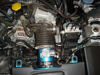
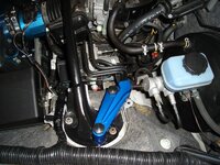
Oh, I did install the Axial Flow master cylinder brace and Race Roots clutch pedal bracing. I did take some pictures of those and will post them up tomorrow. For some reason when I took the Axial Flow brace off to do the coils I couldn't get it back on, feels like there just aren't enough threads on the front struts to permit the bolts to grab (not sure why this is as I didn't change any of that).

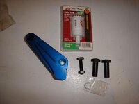
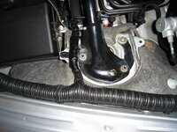
For what it's worth, while the clutch bracing is worthwhile I feel the execution leaves something to be desired. The instructions are lacking, and I had to shim one piece in order to have it line up with the firewall through stud. Plus there is "zero" clearance for the nuts so you will have to use a crow's foot wrench in order to tighten the two for the through studs. I can see where this is a necessity given the tight quarters, but it would be nice if this was referenced in the instructions.

In case my qualifications for mechanical prowess are called into question over this, I have been working as a shipboard engineer for over 20 years. I know how to turn a wrench (righty tighty, lefty loosey) and cannot tell you how many times I have had to disassemble/reassemble equipment without a manual. So I am not a noob.
 
Thanks for all the great write-ups and pics.

I felt the same way about the RR Clutch brace. I ended up installing it without following many steps of the directions due to fitment issues. There are definately some tight clearences to deal with.

Looks like the 8 is really coming along!
 
Okay, revisiting the Axial Flow master cylinder brace (finally). The first picture shows what comprises the brace along with the important hole saw. There are two internally threaded bolts that hold the brace in position. This fits over the front strut brace which has to be modified by cutting a hole over the outer suspension attachment point. I didn't take a picture initially as it was later at night, but what I did first was to estimate where it was and drilled a pilot hole. First one was a little off so drilled another one that was spot on. Keep in mind there is side-to-side adjustability in the factory strut bar so you have some wiggle room there. What I did next was dumb, I didn't really measure the size drill I needed so I proceeded to drill the hole to the largest size I did have. That is the second picture. I did make sure I was still aligned where I needed to be and took a measurement of the base of the brace. Went the Ace the next day and bought the hole saw, note that I used a 1 1/4" while AFE site recommends 1 1/2" or larger. The 1 1/4" works if you have it all lined up. So I eyeballed the hole saw centered and drilled away. This is pretty difficult as you are dealing with compound curves on the base of the strut bar which tends to move the saw around. While it would have been somewhat easier if I had used the hole saw from the beginning (with the pilot drill bit serving to keep it centered) it would still be hard.

Once that was done I put it in place and checked my alignment. With everything looking good I filed the edges of the hole and then gave the disturbed areas a quick coat of spray paint. Once that was dry the strut bar went back on followed by the master cylinder brace. Note that it did touch the strut bar in one spot about halfway along the front edge, I just took a ball peen hammer and gave it a couple of quick raps. The bolt and lock nut have to be put on first, then place the brace over the two suspension points and use the internally threaded bolts to attach it. Then unscrew the bolt until it touches the master cylinder and lock it in place with the lock nut. The last picture is how it looks when you are done.
 

Attachments

  • 012.jpg
    012.jpg
    50.3 KB · Views: 188
  • 013.jpg
    013.jpg
    96.1 KB · Views: 199
  • 022.jpg
    022.jpg
    102.3 KB · Views: 216
And just because I can, here's how to replace your sunvisor (passenger's side shown, driver's a mirror image). Lower the visor and remove the two Phillip's head screws. Unclip the inside hinge and gently pull the visor down to expose the wiring. Disconnect the wires at the white connector. Then just reverse the steps to put the new one on. Note that it is very easy to start the screws and cross-thread them (I noticed this mainly on the outside screw on both sides). They should go in easily, if you turn it around 1/2 turn and it gets tight then pull it back out and try again. Be aware that they will be going in on an angle and that might help.

The last picture shows the two old visors and how they failed. The one with the hinge completely out was the driver's side. You can see how the passenger's side was starting to separate along the same seam.
 

Attachments

  • 08-13-2010 001.jpg
    08-13-2010 001.jpg
    58.5 KB · Views: 192
  • 08-13-2010 002.jpg
    08-13-2010 002.jpg
    56.8 KB · Views: 189
  • 08-13-2010 004.jpg
    08-13-2010 004.jpg
    51.9 KB · Views: 193
Thanks for all the great write-ups and pics.

I felt the same way about the RR Clutch brace. I ended up installing it without following many steps of the directions due to fitment issues. There are definately some tight clearences to deal with.

Looks like the 8 is really coming along!

Thanks. I do hope all this helps someone. I won't bother writing up anything about the RR clutch pedal bracing as there is no point in my duplicating your good post.

Yes, she is coming along nicely. I'm really looking forward to getting the sideskirts and rear flares on. Also the suspension with a good alignment, as I know the handling is much more capable than what we have now with the coilovers. I'm still waiting to hear about the front sway bar. The grounding kit is on its way now so will probably be putting that in next week. No one in town has the fuel pump tool I need (and using a screwdriver and pin punch didn't work at all) so I have to order one of those.
 
Received my Flex Innovations grounding kit today, so that will be going on in a few days.
 
Well I decided to go ahead and install the grounding kit. Excellent instructions were included so that went off well. Since I removed the battery negative I had to reset the DCS system (this is outlined in the owner's manual). What you have to do is turn the key on, put the steering wheel hard over clockwise, then put it hard over counterclockwise. The DCS and traction lights should then go out.

I also swapped over the rear upper spring perches from the used stock shocks I bought to the Tokico D-Specs in order to prepare them for installation. Getting tired of waiting for this front sway, I sent a query off to the vendor I bought it from. Hopefully I'll get an answer tomorrow on that.
 
Back