
Hey guys, I wrote this for Haltechs Mazdaspeed board but know it is hard to find. I wanted to share the info for everyone to have free access to. This applies to the Speed3, Speed6, and DISI CX-7 vechicles.
I tackled a Speed 3 CDFP build at the CP-E/PG/DC meet last weekend and found it to be very simple. The following write up is hopefully going to help a bunch of you guys out and save you a ton of cash. Thank knyghtryda for the pictures, Darksun280 for the pump/donor Speed3, mrlilguy157 for the internals and info, and lastly me CraigHJR if the car runs afterwards.
Tools; E8 inverted torx, 17&19mm open end wrenches, one zip tie, 18mm deep 3/8” socket and long handle ratchet, bench vice with soft jaws and possibly a second set of hands, needle nose pliers, small dish of gas, misc 10mm wrenches and sockets.
Start with the car cold preferably.Remove the smaller blue relay in the under hood fuse box that says “circuit“.
Start the car and it should die when the fuel pressure runs low in 10 seconds. (if not the car being cold means the gas can't really catch fire though it will spray out at high pressure)Remove the entire battery box/ecu and turbo inlet hose if you want to make things easier for your self.
Locate the solid steel line under the CDFP and put a zip tie an inch under the 19mm nut.
This keeps the nut from wandering too far down the line.
Remove the 2 upper fuel lines and electrical connector.
The yellow clip hugs the plastic and has to be opened on both sides while slid out.
The blue clip has a twist motion to release the line.
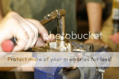
Simultaneously use the 17mm open end to hold the lower base of the CDFP (this CAN NOT SPIN!!!) and the 19mm to break the nut loose (it will spin off easily once broken loose).
Use the E8 inverted torx to remove the 3 screws (back them out evenly as to not cock the spring loaded pump mechanism).
I will say that all that was the hard part and things will be easier from here on out.We are starting with this.

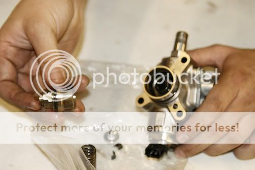
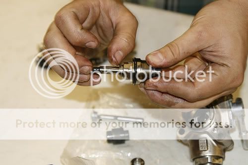
First pull the spring and stock plunger straight out of the pump. This is the stock plunger (left) and upgrade internals and stock spring(right).

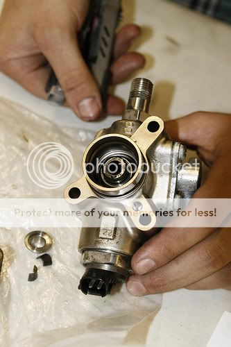
Now support the pump in the bench vice a grab a buddy to steady this thing. Be careful of your lines and sealing surfaces against the vice. Remove the 18mm nut that is now exposed where the spring came off. Righty tighty and lefty loosey.
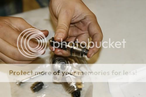
Here you see the 18mm nut assembly removed.
Now gently use needle nose pliers to lift the stock piston out. Notice the small shoulder and large shoulder on the piston. The large side points out towards you.
Now dip all the reused and new parts in gasoline and then slide the upgrade piston and shaft into the 18mm cap. The small end with the retainer groove will be outside the pump. It is unclear if the internals come with the pistons on the shafts already but make sure yours looks like pictured in the first steps above before forcing anything together.
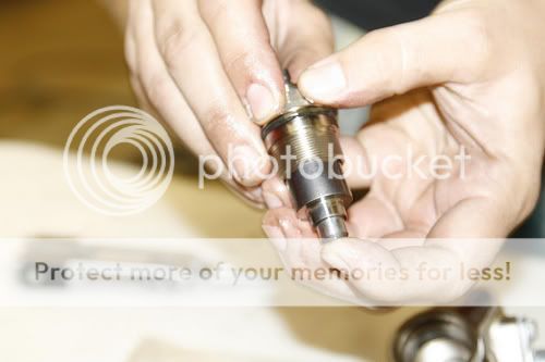
With your finger push the shaft to reveal as much of the retainer groove side through the 18mm nut.
Now slide the spring over the external side of the shaft and seat it on the grove it originally came off of. The spring retainer goes on next with the centering dish going into the spring. Put on the 2 retainer halves and balance everything. Push the retiner end into the assembly jamming the retainer into the spring retainer. The spring is now centered and assembled like pictured below.
Let this assembly sit in gasoline for a few minutes and take a breather if you want. This pic is out of order in the build sequence you should have the spring installed at this point before reassambly.

Make sure no foreign objects fell into your pump and begin to screw the assembled spring and piston assembly into the pump housing by hand.

Once your confident the threads are engaged properly put that deep 18mm over the whole spring and tighten her down. I was not given a spec for this but it is very tight to remove so make it very tight. Again beware of the o-ring, fuel lines and now spring sticking up into the socket. I would say the pump is ready for reinstallation now. Put some fresh oil on the tip of the spring side that rides the camshaft and the o-ring. Use the 3 E-8’s to evenly and slowly draw the pump onto the head. Also be careful to not bend or mutilate the threads on the 17/19 mm stuff underneath by slightly wiggling the steel line downward to allow an even seating as the pump nears its final installed position. Make sure to hold the 17 and do not allow it to spin at all while putting the 19mm nut on. Do not cross thread the 19mm it will spin on freely by hand until the very last turn.
If you made it this far I hope you can put everything else back together paying special attention to the turbo inlet hose being tightened down properly to the turbo.
You should disable the coil packs to allow the engine to crank and build up fuel pressure slightly before you just start the car up. There is a black or gray connector right next to the coil on cylinder 4 that will disconnect them all. If all is well you will be up and running now. If not you probably have a lot of noise and a lean condition which will lead you to be sitting in the same spot as Randy!!!

I tackled a Speed 3 CDFP build at the CP-E/PG/DC meet last weekend and found it to be very simple. The following write up is hopefully going to help a bunch of you guys out and save you a ton of cash. Thank knyghtryda for the pictures, Darksun280 for the pump/donor Speed3, mrlilguy157 for the internals and info, and lastly me CraigHJR if the car runs afterwards.
Tools; E8 inverted torx, 17&19mm open end wrenches, one zip tie, 18mm deep 3/8” socket and long handle ratchet, bench vice with soft jaws and possibly a second set of hands, needle nose pliers, small dish of gas, misc 10mm wrenches and sockets.
Start with the car cold preferably.Remove the smaller blue relay in the under hood fuse box that says “circuit“.
Start the car and it should die when the fuel pressure runs low in 10 seconds. (if not the car being cold means the gas can't really catch fire though it will spray out at high pressure)Remove the entire battery box/ecu and turbo inlet hose if you want to make things easier for your self.
Locate the solid steel line under the CDFP and put a zip tie an inch under the 19mm nut.
This keeps the nut from wandering too far down the line.
Remove the 2 upper fuel lines and electrical connector.
The yellow clip hugs the plastic and has to be opened on both sides while slid out.
The blue clip has a twist motion to release the line.
Simultaneously use the 17mm open end to hold the lower base of the CDFP (this CAN NOT SPIN!!!) and the 19mm to break the nut loose (it will spin off easily once broken loose).
Use the E8 inverted torx to remove the 3 screws (back them out evenly as to not cock the spring loaded pump mechanism).
I will say that all that was the hard part and things will be easier from here on out.We are starting with this.
First pull the spring and stock plunger straight out of the pump. This is the stock plunger (left) and upgrade internals and stock spring(right).
Now support the pump in the bench vice a grab a buddy to steady this thing. Be careful of your lines and sealing surfaces against the vice. Remove the 18mm nut that is now exposed where the spring came off. Righty tighty and lefty loosey.
Here you see the 18mm nut assembly removed.
Now gently use needle nose pliers to lift the stock piston out. Notice the small shoulder and large shoulder on the piston. The large side points out towards you.
Now dip all the reused and new parts in gasoline and then slide the upgrade piston and shaft into the 18mm cap. The small end with the retainer groove will be outside the pump. It is unclear if the internals come with the pistons on the shafts already but make sure yours looks like pictured in the first steps above before forcing anything together.
With your finger push the shaft to reveal as much of the retainer groove side through the 18mm nut.
Now slide the spring over the external side of the shaft and seat it on the grove it originally came off of. The spring retainer goes on next with the centering dish going into the spring. Put on the 2 retainer halves and balance everything. Push the retiner end into the assembly jamming the retainer into the spring retainer. The spring is now centered and assembled like pictured below.
Let this assembly sit in gasoline for a few minutes and take a breather if you want. This pic is out of order in the build sequence you should have the spring installed at this point before reassambly.
Make sure no foreign objects fell into your pump and begin to screw the assembled spring and piston assembly into the pump housing by hand.
Once your confident the threads are engaged properly put that deep 18mm over the whole spring and tighten her down. I was not given a spec for this but it is very tight to remove so make it very tight. Again beware of the o-ring, fuel lines and now spring sticking up into the socket. I would say the pump is ready for reinstallation now. Put some fresh oil on the tip of the spring side that rides the camshaft and the o-ring. Use the 3 E-8’s to evenly and slowly draw the pump onto the head. Also be careful to not bend or mutilate the threads on the 17/19 mm stuff underneath by slightly wiggling the steel line downward to allow an even seating as the pump nears its final installed position. Make sure to hold the 17 and do not allow it to spin at all while putting the 19mm nut on. Do not cross thread the 19mm it will spin on freely by hand until the very last turn.
If you made it this far I hope you can put everything else back together paying special attention to the turbo inlet hose being tightened down properly to the turbo.
You should disable the coil packs to allow the engine to crank and build up fuel pressure slightly before you just start the car up. There is a black or gray connector right next to the coil on cylinder 4 that will disconnect them all. If all is well you will be up and running now. If not you probably have a lot of noise and a lean condition which will lead you to be sitting in the same spot as Randy!!!
Last edited:
