$2008 GRM Challenge – Turbo AWD Mercury Tracer LTS

kcbhiw

What "Lifestyle"?
Contributor
:
64 Valves, 16 Cylinders, 7.2L, 622 HP
After spending three years on the Miata and taking third last year, it's time to head in a different direction. Something new and quite different must be built – something other than a car with a turbo slapped on and a paint job.

Enter my '91 Mercury Tracer LTS. That's right, a four door sedan. Last May (2007), I came across a post wherein the poster stated his co-worker was getting rid of a Tracer, trim level unknown. It was stated that the head gasket was blown. The cost? “Just make it disappear and it was yours”. My first car was a '96 Ford Escort sedan, so I have a bit of a soft spot for these cars and I couldn't beat free. I was in and committed to pick up the car. I was fully expecting it to be equipped with the lethargic Ford 1.9L SEFI and automatic transmission found in most of the specimens.

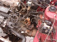
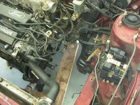
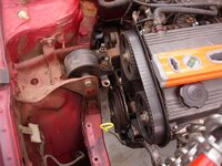
To my surprise when I arrived, I first noticed the identifying lip wing of the LTS, then looked inside and noticed it had a manual transmission and power-nothing. Super-score #1. Ultimately, the car is equipped with rear disk brakes, Mazda 1.8L BP, etc. Basically, it's a first gen Protege with all the Mazda gear in a slightly different package.

Moving on, the engine indeed had a blown head gasket and severely seized water pump. I picked up a replacement engine from a friend for the price of $50. A weekend later and a bit of wrenching and she ran perfectly. The car sat until November or so while I tried to decide what I was going to do with it. The GRM Challenge was always an option and after weighing all of my choices, I chose to go to with a second challenge build :).

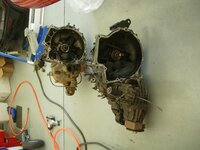
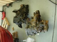
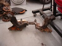
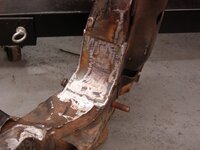
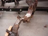
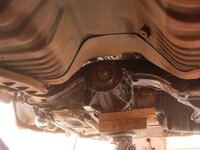
In order of the plan, sure there will be suspension work, a nifty paint job, and obviously a turbo. But that just isn't enough. I thought I might undertake the task of making all four wheels turn under power. That's right, AWD. There are several Mazda AWD options out there, foremost, the 323 GTX.

I was fortunate enough to score a rather rough '88 GTX, all gear included with exception of the turbo, manifolds, and drive shaft. Price: $200. Super-score #2. As a side note, the seller originally offered it to me for $250, but upon arrival, he knocked off $50 AND gave me a beer. He was extremely excited to see it go (that's a story in itself).

The build started several months ago , actually, but I thought I'd make a bit of significant headway before I threw up a build thread only to later discover that things just wouldn't work out. That's not to say that they still won't in the end. There's a TON of work left to do.

For those not familiar with the challenge, information on the $2008 Grassroots Motorsports Challenge is http://grassrootsmotorsports.com/events/2008-challenge/

On to the build:

The Challenger:
DSCF0227.JPG


DSCF0228.JPG


DSCF0232.JPG


The Donor:
DSCN5279.JPG


DSCN5280.JPG


DSCN5281.JPG
 
Last edited:
The Transmission

Below is a comparison of the two transmissions and what I have to work with. They're quite a bit different and really aren't meant to be interchangeable. Fortunately, the GTX and Tracer flywheels, clutch disk, and pressure plates are identical.

It's pretty nasty as it is covered in oil residue and general funk. I'll clean it, as well as everything else, later as I plan to first completely assemble everything, then later tear down of the car to clean and paint.

I hope I don't break it, they're not easy to come by :(....
 

Attachments

  • DSCN5202.JPG
    DSCN5202.JPG
    488.6 KB · Views: 1,168
  • DSCN5204.JPG
    DSCN5204.JPG
    437.2 KB · Views: 1,039
  • DSCN5206.JPG
    DSCN5206.JPG
    305.5 KB · Views: 1,224
  • DSCN5207.JPG
    DSCN5207.JPG
    334.3 KB · Views: 1,048
Last edited:
The Starting Point

The best place to begin when wanting to drive the rear wheels is obviously moving the power from the engine to the back. Fitting the AWD transmission is the first step. I knew this wouldn't be easy and that has proved true. The only thing that lined up properly between the BG chassis and the BF transmission were the block to transmission bell housing bolt points. Even the BP oil pan bolt holes don't align. Once I actually got the transmission bolted to the engine, the headaches began.

The front subframe was the biggest hurdle. Lots of cutting. I have spent innumerable hours trying to get it to clear.....measure, drop the engine, drop the subframe, cut the subframe, install the subframe, raise the engine, measure, drop the subframe....rinse/wash/repeat. The subframe has been off of the car no less than 15 times. As it turns out I removed way too much metal and had to rebuild a bit of the center of the subframe. Using scrap 10 gauge steel plate I recovered from the work dumpster, I cut and welded plates to cover the transmission clearances in the subframe.


Enough rambling and on to the pics....
 

Attachments

  • DSCN5213.JPG
    DSCN5213.JPG
    380.1 KB · Views: 1,044
  • DSCN5214.JPG
    DSCN5214.JPG
    652.3 KB · Views: 966
  • DSCN5216.JPG
    DSCN5216.JPG
    630.3 KB · Views: 910
  • DSCN5215.JPG
    DSCN5215.JPG
    578 KB · Views: 917
  • DSCN5224.JPG
    DSCN5224.JPG
    512.7 KB · Views: 972
Last edited:
Front Subframe Continued...

Rebuilding the subframe allowing transmission clearances...


Pay no attention to the quality of welding ;).
 

Attachments

  • DSCN5347.JPG
    DSCN5347.JPG
    350.3 KB · Views: 865
  • DSCN5352.JPG
    DSCN5352.JPG
    360.8 KB · Views: 814
  • DSCN5354.JPG
    DSCN5354.JPG
    384.8 KB · Views: 784
  • DSCN5358.JPG
    DSCN5358.JPG
    298.5 KB · Views: 793
  • DSCN5359.JPG
    DSCN5359.JPG
    329.6 KB · Views: 808
Last edited:
Front Subframe Continued...

More quality welding on the subframe (the bigger the blob, the better the job :D)...
 

Attachments

  • DSCN5361.JPG
    DSCN5361.JPG
    398.3 KB · Views: 815
  • DSCN5360.JPG
    DSCN5360.JPG
    318.8 KB · Views: 771
  • DSCN5363.JPG
    DSCN5363.JPG
    349.7 KB · Views: 678
  • DSCN5364.JPG
    DSCN5364.JPG
    353.3 KB · Views: 733
  • DSCN5365.JPG
    DSCN5365.JPG
    342 KB · Views: 792
Last edited:
Driver's Side Tranny Mount

Did I mention that nothing fit? This includes the angle of the engine. In the BG chassis, the engine is tilted forward about 8-10 degrees. The BF chassis has no tilt in the engine. With the BF AWD transmission bolted to the BP using the stock engine angle, the rear output shaft pointed upward toward the floor pan.

At this point, one might ask, why not just use a J-spec (JDM, y0) BG transmission. The primary reason is the cost. I'd rather offset cost by labor, since this is a hobby and all. Furthermore, that's the goal of the challenge: minimal cost.

Anyway, the next best place to give focus to would be the passenger's side engine mount, considering the remaining three would have to be custom made. I have tried various mounts from various cars throughout the junkyard, but alas, nothing seemed to provide the proper arrangements, though several were very close. The current arrangement includes 3 washers under the aft bolt (there are two). This will be corrected and finalized later ;). However, the engine sat as I wanted it to.


The first mount to be manufactured was the driver's side transmission mount. Using most of the BG chassis mount as it sat, I made an adapter plate to bolt to the tranny. The spacers were made using a hole saw cut through a 1 steel block.
 

Attachments

  • DSCN5243.JPG
    DSCN5243.JPG
    390.5 KB · Views: 899
  • DSCN5241.JPG
    DSCN5241.JPG
    401.7 KB · Views: 840
  • DSCN5250.JPG
    DSCN5250.JPG
    492.8 KB · Views: 863
  • DSCN5253.JPG
    DSCN5253.JPG
    460.8 KB · Views: 818
Last edited:
Front Tranny Mount

The front transmission mount was frighteningly easy. I perused the junkyard for a mount and/or bracket that would be suitable. I came across an Escort LX-E (the same thing as the Tracer LTS Mazda bits and all) with an automatic transmission. I noticed the front mount bracket shared a similar bolt pattern to that of the GTX's. In short, I brought it home, bolted it to the transmission using 2 of the 3 bolts and began fitting the actual mount. Fortunately, with the mount bolted the the bracket, 3/8 steel plate fit the gap between the mount and the cross member perfectly while minding the desired vertical engine geometry. A bit of cutting and drilling and the plate was fitted. To complete the attachment of the bracket to the transmission, the third bolt hole had to be drilled at a lower position.

2 out of 3 mounts were set, and the engine finally rested without the assistance of a lift. Yay!

The first two images compare the differences in the mounts (From left to right: GTX, BG-Auto Transmission, BG-Manual Transmission).
 

Attachments

  • DSCN5260.JPG
    DSCN5260.JPG
    282.5 KB · Views: 740
  • DSCN5259.JPG
    DSCN5259.JPG
    316.6 KB · Views: 801
  • DSCN5261.JPG
    DSCN5261.JPG
    458.2 KB · Views: 680
  • DSCN5256.JPG
    DSCN5256.JPG
    409.2 KB · Views: 740
  • DSCN5258.JPG
    DSCN5258.JPG
    416.6 KB · Views: 717
Last edited:
Front Cross Member

Of course, no one said this would be easy. During the fitting of the main subframe, the cross member was modified to fit the front transmission mount and clear the transmission rear output housing. A bit of cutting, a piece of rigid gas pipe, steel plate, and welding and it's all together. I need to make one more notch on the driver's side of the piece to clear a bolt in the tranny, but I'll also save that for later.
 

Attachments

  • DSCN5270.JPG
    DSCN5270.JPG
    310.9 KB · Views: 777
  • DSCN5271.JPG
    DSCN5271.JPG
    386.9 KB · Views: 685
  • DSCN5273.JPG
    DSCN5273.JPG
    406.5 KB · Views: 695
  • DSCN5272.JPG
    DSCN5272.JPG
    405.2 KB · Views: 697
  • DSCN5276.JPG
    DSCN5276.JPG
    480.5 KB · Views: 774
Last edited:
Steering Rack Elevation

After reassembling everything and hoping for the best, the transmission made contact with the steering rack. I had been expecting this, but was hoping to avoid it. Nonetheless, it was a situation that required correction. Eventually, the steering rack was raised 3/4 to provide ample clearance of the transmission. This obviously creates another inherent issue of the actual steering column becoming too long. Fortunately, a roughly 3 extension of sorts was build into the column. I was able to cut the necessary length from this and reconnect the column to the rack. The angle of the various universal joints in the column is a bit more acute, for lack of a better word, but I don't think it should present a significant problem.


Currently, I'm lacking a mounting point on the driver's side of the steering column as it had to be cut off while clearancing the subframe. I will later add this bolting point during the teardown/rebuild of the car.
 

Attachments

  • DSCN5370.JPG
    DSCN5370.JPG
    387.4 KB · Views: 745
  • DSCN5371.JPG
    DSCN5371.JPG
    380.5 KB · Views: 666
  • DSCN5374.JPG
    DSCN5374.JPG
    349.6 KB · Views: 660
  • DSCN5375.JPG
    DSCN5375.JPG
    473.1 KB · Views: 676
  • DSCN5376.JPG
    DSCN5376.JPG
    503 KB · Views: 711
Last edited:
Front Drive Gear

Ahh...the all important aspect of getting power to the wheels. Better yet, how about doing so with parts from no less than 5 different car models (Tracer, 626, GTX, Ford Aspire, and Mercury Capri)?

The alignment of the entire forward drive line has been a challenge to say the least. The GTX transmission moved the axles forward about 2.5” from where they were in the tracer. That leads to some funky axle geometry and reduced axle life. The goal was to find a way to move the wheel center's forward and therefore increase the car's wheelbase.

Enter the 3rd gen Protege. I updated the front control arms on a friend's car about a year ago and held on to the old ones for the reason of “just in case” (I never throw anything away). Sure enough, the length and width of the CA was exactly what I needed. The first drawback was that the rear mounting point was a rubber bushing as opposed to bracketed rod found on the Tracer. The second was that the ball joint pin was slightly larger not allowing it to slide into the bottom of the steering knuckle. During a junkyard search for some parts, I noticed that the control arms found on the 2nd gen MX6/626 were nearly identical to those found on the later Protege, but the rear mounting point was a bracketed rod, nearly identical to the Tracer's. That eliminated a significant amount of customization for said mounting point. I simply manufactured a spacer for the rod, trimmed the inboard pinch weld, and trimmed the front bushing tube and it fit perfectly and placed the knuckle nearly where I wanted it to be.

The first image compares several control arms that were likely candidates. From left to right: Tracer (BG), GTX (BF), '96 626, '99 Protege. The second image depicts the comparison between the 626's and 3rd gen Protege's control arms. The third shows the geometry differences between the Tracer's and 626's control arms.
 

Attachments

  • DSCN5301.JPG
    DSCN5301.JPG
    335.1 KB · Views: 717
  • DSCN5300.JPG
    DSCN5300.JPG
    298.3 KB · Views: 777
  • DSCN5302.JPG
    DSCN5302.JPG
    336.9 KB · Views: 687
  • DSCN5315.JPG
    DSCN5315.JPG
    343.7 KB · Views: 664
  • DSCN5318.JPG
    DSCN5318.JPG
    403.7 KB · Views: 757
Last edited:
Front Drive Gear (Con't)

Considering that this is a budget build, custom axles aren't in the budget, at least right now. Unfortunately, those from the Tracer don't fit the transmission. Therefore, I was forced to use the GTX's axles. Furthermore, this requires the use of the GTX knuckles and spindles. However, using the GTX knuckle/spindle assembly required the use of 4x114.3 bolt pattern wheels as opposed to the 4x100 bolt pattern wheels that are more commonly found.............what a mess.

Bolting up the GTX's knuckles would have worked just fine. However, I noticed that the the steering arm between the GTX's knuckle and the arm on a knuckle I had lying around from a Capri were different....the Capri's arm was about 2 inches lower. If I were to use the Capri's knuckle, bump steer would be improved once the car (Tracer) was lowered. Additionally, the spindle between the GTX and the Capri are identical.

Being the stubborn person that I am, I'd rather not buy any additional wheels as I have several sets employing the 4x100 bolt pattern already laying around. My goal was to find a way to use those wheels with the Capri knuckles without the use of any adaptors or the like. My answer was found in the Ford Aspire.


The Aspire's spindles share the same axle diameter and spline count as the GTX/Capri. It uses the same bearing part numbers as well. I picked up a pair of knuckles from an Aspire at the junker and compared what I had. The knuckle castings were nearly the same as the Capri's with the exception that the lower control arm ball joint attachment was closer to the hub's center. This could pose a problem with the suspension geometry once the car (Tracer) is lowered. So the decision was made to use the Capri knuckles with Aspire spindles. With new bearings installed on the driver's side assembly, all was ready for a test fit between the control arm, knuckle, axle, brake caliper, etc.
 

Attachments

  • DSCN5305.JPG
    DSCN5305.JPG
    384.7 KB · Views: 838
  • DSCN5307.JPG
    DSCN5307.JPG
    381.4 KB · Views: 827
  • DSCN5309.JPG
    DSCN5309.JPG
    430.2 KB · Views: 718
  • DSCN5308.JPG
    DSCN5308.JPG
    469.7 KB · Views: 710
  • DSCN5343.JPG
    DSCN5343.JPG
    389 KB · Views: 730
Last edited:
Front Drive Gear (Con't)

Since the 323GTX employs the B6T, the engine block length is significantly shorter than that of the BP that is used in the tracer. This posed a problem when installing the intermediate axle shaft; none of the mounting holes aligned on the longer engine.

I discovered (the hard way) that the bearing support for the intermediate shaft was cast iron and not very weldable. I therefore fabricated a bracket of sorts to pinch the bearing support against the block and securing it with the mounting points found on the BP. The bearing support is secured by 3 bolts and this bracket accounts for two of them. I simply drilled a hole in the bearing support to allow access to the third bolt hole.

Apologies for the lack of pics detailing the placement and overall assembly.
 

Attachments

  • DSCN5337.JPG
    DSCN5337.JPG
    411.1 KB · Views: 716
  • DSCN5336.JPG
    DSCN5336.JPG
    497.3 KB · Views: 641
  • DSCN5338.JPG
    DSCN5338.JPG
    274.5 KB · Views: 728
  • DSCN5339.JPG
    DSCN5339.JPG
    313.5 KB · Views: 657
  • DSCN5340.JPG
    DSCN5340.JPG
    297.8 KB · Views: 700
Last edited:
Front Drive Gear (Con't)

With the complete reworking of the front drive train, another problem was presented, of course. Since the lower mounting point of knuckle was moved forward nearly two inches, ultimately increasing the wheelbase of the car, the caster angle was severely changed. Furthermore, the OE springs rub the unibody. This will be corrected later when time permits to run through everything with a fine tooth comb.

As anticipated (read: hoped), the Tracer's brake caliper affixed to the knuckle perfectly and the rotor was centered in the caliper as it should be. Whew...that was easy.
 

Attachments

  • DSCN5378.JPG
    DSCN5378.JPG
    286.8 KB · Views: 722
  • DSCN5377.JPG
    DSCN5377.JPG
    273 KB · Views: 698
  • DSCN5379.JPG
    DSCN5379.JPG
    304.3 KB · Views: 714
Last edited:
Shifter Assembly

Now that the front drive train is nearly complete, the time arrived to sort out the gear shifter and linkage. The BG uses a rod actuated shifting mechanism whereas the BF uses cables. The BG's shift linkage resides beneath the car in the exhaust tunnel while the BF's cables reside on the interior passing through the firewall.

The first step was to fit the GTX's shifter assembly. Both the Tracer's and GTX's assembly is secured by four bolts. The GTX assembly's two forward most bolts matched perfectly to the Tracer's mounting points only requiring two holes to be drilled in the unibody for the rear mount points.

The shift cables were installed just as easily. To my fortune, a hole exists in the firewall of the BG that perfectly matches that of the BF. It was covered only by a simple plate and even has the two mounting studs to secure the cables in the exact manner as the BF.

I simply removed the blocking plate, passed the cables through, and connected them to the shifter assembly and transmission. Gotta love it.

14
 

Attachments

  • DSCN5394.JPG
    DSCN5394.JPG
    242.3 KB · Views: 720
  • DSCN5397.JPG
    DSCN5397.JPG
    361.1 KB · Views: 663
  • DSCN5398.JPG
    DSCN5398.JPG
    387.8 KB · Views: 628
  • DSCN5401.JPG
    DSCN5401.JPG
    459.7 KB · Views: 686
  • DSCN5399.JPG
    DSCN5399.JPG
    460.3 KB · Views: 745
Last edited:
Wow great thread, I just hope the welding holds up when you bring the car out on the track.
 
Curious---didn't Mazda make an AWD BG Protege? Protege GTX???

I understand the $2008 budget--but if that was a non-issue, it would seem to me that it would be easier to source parts this way than from a 323GTX et. al.???

Nice build, nonetheless!
 
Kevin, you are ******* insane! Well done, my friend! :D
 
Back